Short-circuit fault current-limiting transformer

A technology for short-circuit faults and transformers, which is applied in the field of circuit fault current limiting and can solve problems such as poor short-circuit resistance of transformers, and achieve the effects of improving short-circuit resistance and prolonging life

Inactive Publication Date: 2017-07-21
秦伟喆 +2
View PDF3 Cites 4 Cited by
  • Summary
  • Abstract
  • Description
  • Claims
  • Application Information

AI Technical Summary

Problems solved by technology

[0004] The invention provides a short-circuit fault current-limiting transformer, which solves the problem of poor short-circuit resistance of the transformer

Method used


Image

  • Short-circuit fault current-limiting transformer
  • Short-circuit fault current-limiting transformer
  • Short-circuit fault current-limiting transformer

Examples


Embodiment 1

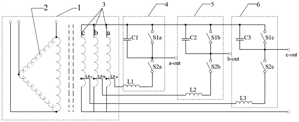
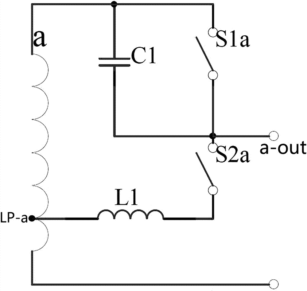
[0021] Such as figure 1 As shown, a short-circuit fault current-limiting transformer, the current-limiting transformer includes a transformer primary coil 2 of a transformer 1, a transformer secondary coil 3 and a short-circuit protection circuit 4, and the transformer secondary coil is composed of three identical secondary coils The side coils a, b, and c are composed of three secondary side coils a, b, and c that are close to 40% of the low-voltage end, respectively lead to a low-voltage tap LP-a, LP-b, LP-c, and the low-voltage tap LP-a is connected to A short-circuit protection circuit 4, the short-circuit protection circuit 4 includes a low-voltage tap LP-a connected in series with the auxiliary reactor L1, short-circuit protection switch S2a, and capacitor C1 in sequence and connected to the high-voltage end of the same coil corresponding to the low-voltage tap LP-a to form a protection branch The capacitor C1 is connected in parallel with the power supply switch S1a at ...


PUM


Abstract

The invention relates to the technical field of circuit fault current limiting, and specifically relates to a short-circuit fault current-limiting transformer. The current-limiting transformer comprises a transformer and short-circuit protection circuits. The secondary coil of the transformer is composed of three identical secondary coils. A low-voltage tap is led out from each of the three secondary coils. One short-circuit protection circuit is connected between each low-voltage tap and the high-voltage end of the corresponding coil. Each short-circuit protection circuit is a current limiting loop in which one low-voltage tap is sequentially connected in series with an auxiliary reactor, a short-circuit protection switch and a capacitor and then connected with the high-voltage end of the corresponding secondary coil, wherein the capacitor is connected in parallel with a power supply switch, and the common joint of the power supply switch and the short-circuit protection switch is connected to a power supply circuit. At the moment when a line fails, a large impedance is added between the power supply and the fault point, and thus, the fault current is limited.

Description

technical field [0001] The invention relates to the technical field of circuit fault current limiting, in particular to a short circuit fault current limiting transformer. Background technique [0002] With the vigorous development of all walks of life in society, the demand for electricity as an energy source has become more prominent, and the capacity of the power grid has expanded rapidly. At the same time, the level of short-circuit current in the power system has also reached a severe level. Safety issues and economic issues force people to do a lot of research and implement some measures passively and actively, and therefore fault current limiting technology has appeared, especially in the past ten years, short-circuit fault current limiting technology has developed rapidly, such as superconducting fault current limiter , power electronic fault current limiter, permanent magnet fault current limiter, etc. are all hot topics of current research, and there are many branc...

Claims


Application Information

Patent Timeline
Patent Type & Authority Applications(China)
IPC IPC(8): H02H9/02H02H7/055
CPCH02H9/02H02H7/055
Inventor 秦伟喆董江涛马金龙谢增辉程前段成林王书坤郑珺祥孙赟尹璐冯磊秦迎悦董尚阳程红英刘开拓马俊丽余可王佑民王建军杨建宇刘建民李明明褚灵云褚文鹏秦宇翔李春生褚新民李志学
Owner 秦伟喆
Why Eureka
Try Eureka