Power supply adaptation device, control method thereof, and control device thereof
A technology of power supply adaptation and control method, which is applied in the direction of circuit devices, battery circuit devices, coupling devices, etc., and can solve the problems that power adapters cannot be directly converted into USBPD power sources, waste of resources, etc.
- Summary
- Abstract
- Description
- Claims
- Application Information
AI Technical Summary
Problems solved by technology
Method used
Image

Examples
Embodiment 1
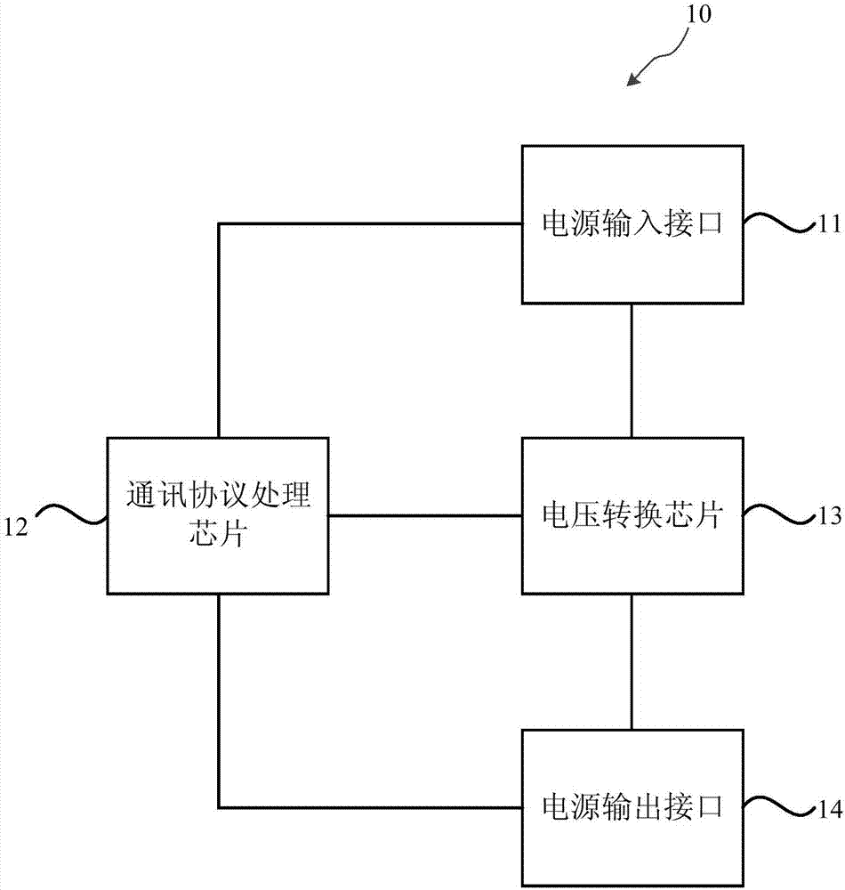
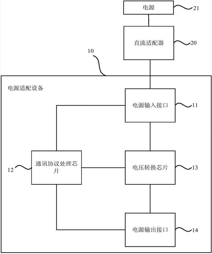
[0031] Figure 1A It is a schematic structural diagram of a power adapter device provided by Embodiment 1 of the present invention. This embodiment is applicable to power adapters and wires of various interfaces, and is electrically connected to electronic devices with a TYPE-C interface to complete charging. Such as Figure 1A As shown, the power adapter device specifically includes: a power input interface 11, a communication protocol chip 12, a voltage conversion chip 13 and a power output interface 14;
[0032] The first detection terminal of the communication protocol chip 12 is connected to the power input interface 11, the second detection terminal of the communication protocol chip 12 is connected to the power output interface 14, and the control terminal of the communication protocol chip 12 is connected to the power input interface 11. The voltage conversion chip 13 is connected;
[0033] The input end of the voltage conversion chip 13 is connected to the power input...
Embodiment 2
[0051] figure 2 It is a control method diagram of a power adapter device provided by Embodiment 2 of the present invention. This embodiment is applicable to the control of any power adapter device. This method can be implemented by the power adapter device provided by the embodiment of the present invention The control device can be implemented by means of software and / or hardware, and the device can be integrated in any device that provides the control function of the power adapter device. Such as figure 2 shown, including:
[0052] Correspondingly, the method of this embodiment includes:
[0053] S210. The communication protocol chip acquires an input voltage value through the first detection terminal.
[0054] Specifically, the power adapter device includes a power input interface, a communication protocol chip, a voltage conversion chip, and a power output interface. The communication protocol chip has three detection terminals which are respectively electrically con...
Embodiment 3
[0067] image 3 A control flow chart of a power adapter device provided by Embodiment 3 of the present invention. In this embodiment, on the basis of the above embodiments, the communication protocol chip obtains the target voltage value through the second detection terminal, including: the The communication protocol chip is on the second detection terminal, and obtains the target voltage value requested by the target device through the PD protocol.
[0068] Correspondingly, the method of this embodiment includes:
[0069] S310. The communication protocol chip acquires an input voltage value through the first detection terminal.
[0070] S320. The communication protocol chip acquires the target voltage value requested by the target device through the PD protocol on the second detection terminal.
[0071] Wherein, the target device is an electronic device electrically connected to the power adapter device. The PD protocol (USB PD protocol) is a concept of power transmission ...
PUM
 Abstract
Description
Claims
Application Information
 - R&D
- Intellectual Property
- Life Sciences
- Materials
- Tech Scout
- Unparalleled Data Quality
- Higher Quality Content
- 60% Fewer Hallucinations
Browse by: Latest US Patents, China's latest patents, Technical Efficacy Thesaurus, Application Domain, Technology Topic, Popular Technical Reports.
© 2025 PatSnap. All rights reserved.Legal|Privacy policy|Modern Slavery Act Transparency Statement|Sitemap|About US| Contact US: help@patsnap.com