Method and device for configuring a reference signal

A technology of reference signal and configuration method, applied in the field of communication, can solve the problems of large system overhead and detection complexity, high coding redundancy, and high reliability requirements of downlink control signaling, so as to improve the effectiveness and improve the spectral efficiency. , the effect of increasing flexibility

Active Publication Date: 2021-10-01
HUAWEI TECH CO LTD
View PDF3 Cites 0 Cited by
  • Summary
  • Abstract
  • Description
  • Claims
  • Application Information

AI Technical Summary

Problems solved by technology

However, due to the high reliability requirements of downlink control signaling, high coding redundancy, and downlink control signaling relying on blind detection, the method of directly increasing the length of the DMRS configuration field will bring large system overhead and detection complexity

Method used


Image

  • Method and device for configuring a reference signal
  • Method and device for configuring a reference signal
  • Method and device for configuring a reference signal

Examples


Embodiment Construction

[0055] Reference will now be made in detail to the various embodiments of the invention, examples of which are illustrated in the accompanying drawings. While described in conjunction with these Examples, it will be understood that they are not intended to limit the invention to these Examples. On the contrary, the present disclosure is intended to cover alternatives, modifications and equivalents, which may be included within the spirit and scope of the present invention as defined in the appended claims. In addition, in the following detailed description of the invention, numerous specific details are set forth in order to provide a thorough understanding of the present invention. It is understood, however, that in practice these specific details of the invention may not be included. In other instances, well-known methods, procedures, components, and circuits have not been described in detail so as not to unnecessarily obscure aspects of the present invention.

[0056] f...


PUM


Abstract

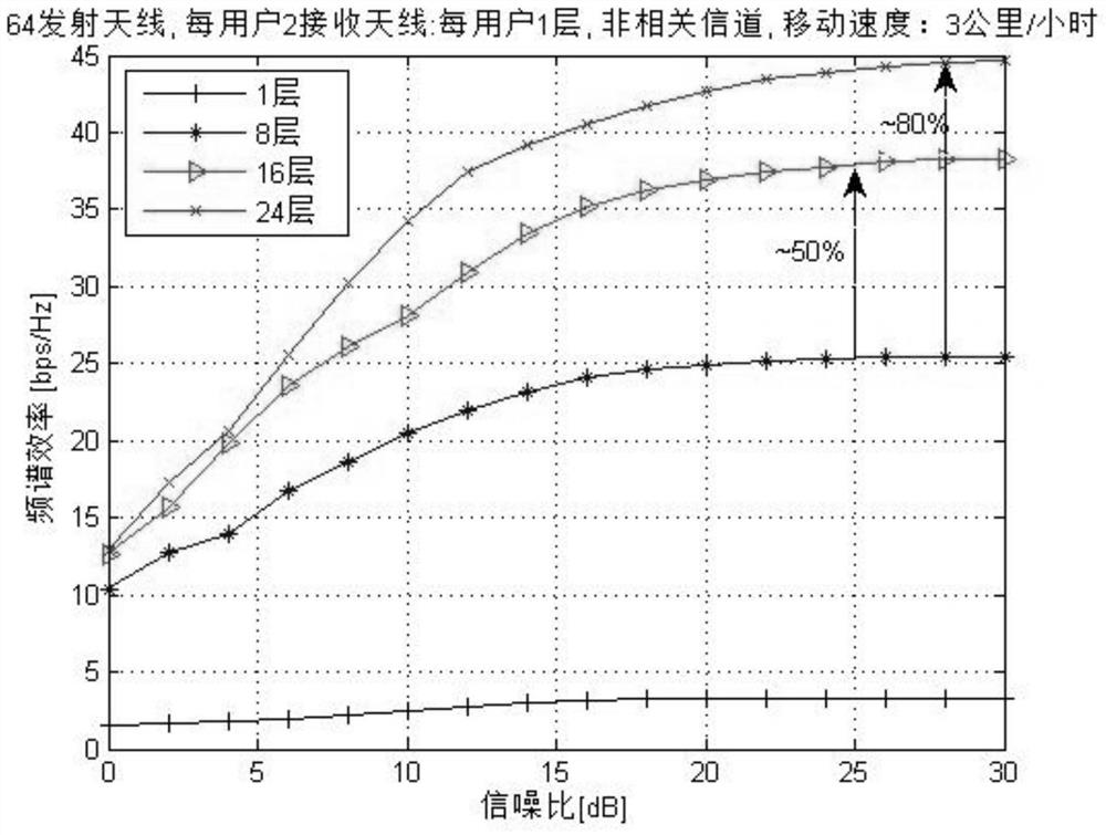
In the embodiment of the present invention, by indicating a double-codeword transmission mode and two single-codeword transmission modes, wherein the two single-codeword transmission modes are distinguished by using the new data indication NDI, so that the available state value of the reference signal configuration increases, and then can support Higher-order (such as 16-layer, 24-layer) MU-MIMO can significantly improve the spectral efficiency of the system, and also increase the flexibility of MU-MIMO configuration and improve the effectiveness of resource scheduling.

Description

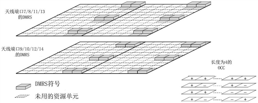
technical field [0001] The present invention relates to the field of communication technologies, in particular to a reference signal configuration method and device. Background technique [0002] In the long-term evolution technology (English: Long Term Evolution; abbreviation: LTE) system, the multiple-input multiple-output (English: Multi-input Multi-output; abbreviation: MIMO) technology supports spatial multiplexing of multi-layer data streams. The demodulation reference signal (English: Demodulation Reference Signal; abbreviation: DMRS or DM-RS) corresponding to the stream needs to maintain orthogonal (English: Orthogonal) or semi-orthogonal (English: Semi-orthogonal) characteristics to avoid interference between data streams . For example, frequency division multiplexing and orthogonal masking (English: Orthogonal Cover Code; OCC) are used between multiple DMRSs corresponding to multi-layer data streams of a single user to realize completely orthogonal DMRS configurat...

Claims


Application Information

Patent Timeline
Patent Type & Authority Patents(China)
IPC IPC(8): H04W72/04H04W72/12
CPCH04W72/0453H04W72/20H04W72/04H04W72/12H04L5/0016H04L5/0017H04L5/0023H04L5/0051H04L5/0092H04B7/0452H04L5/0053
Inventor 刘瑾杭海存毕晓艳陈大庚
Owner HUAWEI TECH CO LTD
Why Eureka
Try Eureka