
Communication cabinet with rain shelter device

A technology for communication cabinets and cabinets, which is applied in the direction of casings/cabinets/drawer parts, electrical equipment casings/cabinets/drawers, electrical components, etc. Increase the maintenance cycle and other issues to achieve the effect of improving equipment maintenance efficiency, facilitating maintenance, and improving work efficiency

Inactive Publication Date: 2017-07-21
CHENGDU ZHENZHONG ELECTRIC
View PDF8 Cites 0 Cited by
  • Summary
  • Abstract
  • Description
  • Claims
  • Application Information

AI Technical Summary

Problems solved by technology

[0005] The present invention aims at the problem that the existing communication cabinet is only used as a carrier of communication equipment and cannot provide a rain shelter for equipment maintainers in rainy days, which increases the maintenance cycle and reduces the maintenance efficiency, and provides a communication cabinet with a rain shelter

Method used


Image

  • Communication cabinet with rain shelter device
  • Communication cabinet with rain shelter device
  • Communication cabinet with rain shelter device

Examples


Embodiment 1

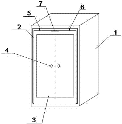
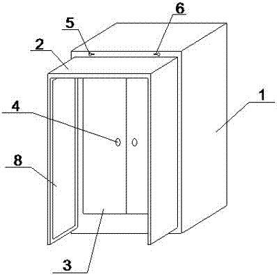
[0038] like figure 1 and 2 As shown, the communication cabinet with a rain shelter includes a cabinet body 1 , wherein a cabinet door 3 and a handle 4 are arranged on the front of the cabinet body 1 , and the handle 4 is connected to the cabinet door 3 . Wherein the front of the cabinet body 1 is provided with a "ㄇ" shaped concave cavity and a rotating block 5, and the back of the cabinet body 1 is provided with a ventilating groove 105, and the concave cavity is located between the cabinet door 3 and the edge of the cabinet body 1. There are slide rails and a pumping plate 2 with a "ㄇ"-shaped structure, the pumping plate 2 is in contact with the slide rail, the rotating block 5 is located above the concave cavity, and the rotating block 5 is connected with a device that restricts the drawing of the pumping plate 2 when it is rotated to a vertical position. Limiting sheet 6.

[0039] In use, when it rains, the cabinet maintainer can adjust the rotating block, rotate the limi...

Embodiment 2

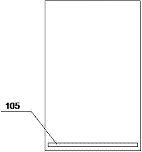
[0041] like image 3 and 4 As shown, the back of the cabinet body 1 has a three-layer structure, which is an inner layer 101, an interlayer 102 and an outer layer 103, the inner layer 101 is provided with a through groove 104, the interlayer 102 is provided with a ventilation channel 9, and the outer layer 103 is provided with Vent groove 105 is arranged. The through groove 104 is located at the top of the inner layer 101, and the ventilation groove 105 is located at the bottom of the outer layer 103. The ventilation passage 9 communicates with the inside of the cabinet body 1 through the through groove 104, and the ventilation passage 9 is connected with the outside through the ventilation groove 105.

Embodiment 3

[0043] like image 3 and 5 As shown, the back of the cabinet body 1 has a three-layer structure, which is an inner layer 101, an interlayer 102 and an outer layer 103, the inner layer 101 is provided with a through groove 104, the interlayer 102 is provided with a ventilation channel 9, and the outer layer 103 is provided with Vent groove 105 is arranged. The through groove 104 is located at the bottom of the inner layer 101, and the ventilation groove 105 is located at the top of the outer layer 103. The ventilation passage 9 communicates with the inside of the cabinet body 1 through the through groove 104, and the ventilation passage 9 is connected with the outside through the ventilation groove 105.


PUM


Abstract

The invention relates to the field of communication cabinets, in particular to a communication cabinet with a rain shelter device. The technical key points are as follows: the communication cabinet comprises a cabinet body, the front of the cabinet body is provided with a cabinet door and a handle, and the handle is connected with the cabinet door; the front of the cabinet body is provided with a PI-shaped concave cavity and a rotating block, and the back of the cabinet body is provided with a venting slot; the concave cavity is arranged between the cabinet door and the edge of the cabinet body, the concave cavity is internally provided with a slide rail and a PI-shaped pulling plate, and the pulling plate is in contact with the inner wall of the concave cavity through the slide rail; and the rotating block is connected with a limiting piece which limits the pulling plate to be pulled out when rotating to a vertical position. The problem that the maintenance cycle of the existing communication cabinet is increased and the maintenance efficiency is reduced as the existing communication cabinet is only used as a communication equipment carrier and cannot provide a rain shelter for equipment maintainers in rainy days is solved.

Description

technical field [0001] The invention relates to the field of communication cabinets, in particular to a communication cabinet with a rain shelter. Background technique [0002] The communication cabinet is a kind of outdoor cabinet, which refers to the cabinet made of metal or non-metal materials that is directly under the influence of natural climate, and does not allow unauthorized operators to enter and operate, providing outdoor equipment for wireless communication sites or wired network site workstations. Equipment for the physical work environment and security systems. [0003] In normal use, communication cabinet suppliers regularly need special personnel to inspect and maintain the communication cabinets. The maintainer of a communication cabinet needs to inspect and maintain multiple communication cabinets a day. Occasionally, it will rain. The communication equipment inside is damp, and maintenance personnel often need to wait for the rain to stop before performin...

Claims


Application Information

Patent Timeline
Patent Type & Authority Applications(China)
IPC IPC(8): H05K5/02
CPCH05K5/0213H05K5/0217
Inventor 王刚胡国波聂海涛
Owner CHENGDU ZHENZHONG ELECTRIC
Learn More