Roll position detection system for rolling mill

A detection system and roll technology, applied in metal rolling, length measuring device, metal rolling, etc., can solve problems such as affecting production efficiency, detecting equipment failure, unable to monitor dynamic position changes of upper and lower rolls, etc., and achieve real-time and accurate control , the effect of efficient production

Active Publication Date: 2018-12-14
PANGANG GRP PANZHIHUA STEEL & VANADIUM
View PDF5 Cites 0 Cited by
  • Summary
  • Abstract
  • Description
  • Claims
  • Application Information

AI Technical Summary

Problems solved by technology

However, it is difficult to measure the axial movement value of the roll due to the influence of temperature, roll cooling water, dust, vibration, and large axial force during dynamic
When the axial movement cannot be known, the roll gap adjustment can only be done based on experience, resulting in defective products caused by a large number of adjustments
At the same time, the position of the upper and lower rolls will also change when passing the steel. Due to the dynamic change, it cannot be accurately measured by the displacement sensor of the rolling mill itself.
The existing method of dynamically measuring the axial position of the bearing seat to determine the dynamic axial position of the roll not only cannot monitor the dynamic position change of the upper and lower rolls, but also has the following problems: 1. The error caused by the gap between the bearing seat and the roll cannot be ruled out ; 2. The gap between the bearing seat and the rolling mill archway cannot be ruled out. Due to the wear of the archway wear plate, the largest measurement error has reached 5mm
But the existing method also has the following problems: one, the support point of the testing equipment on the archway is affected by dust, water mist, etc., the installation is unstable and shakes greatly, and the installation surface is uneven; two, the installation time of the testing equipment is as long as 30- 50 minutes, affecting production efficiency; 3. The working environment such as dust and water affects the detection accuracy of the equipment, and at the same time leads to the failure of the detection equipment; 4. It is impossible to monitor the dynamic change of the position of the upper and lower rolls

Method used


Image

  • Roll position detection system for rolling mill

Examples


Embodiment Construction

[0013] The present invention will be further described below in conjunction with the drawings.

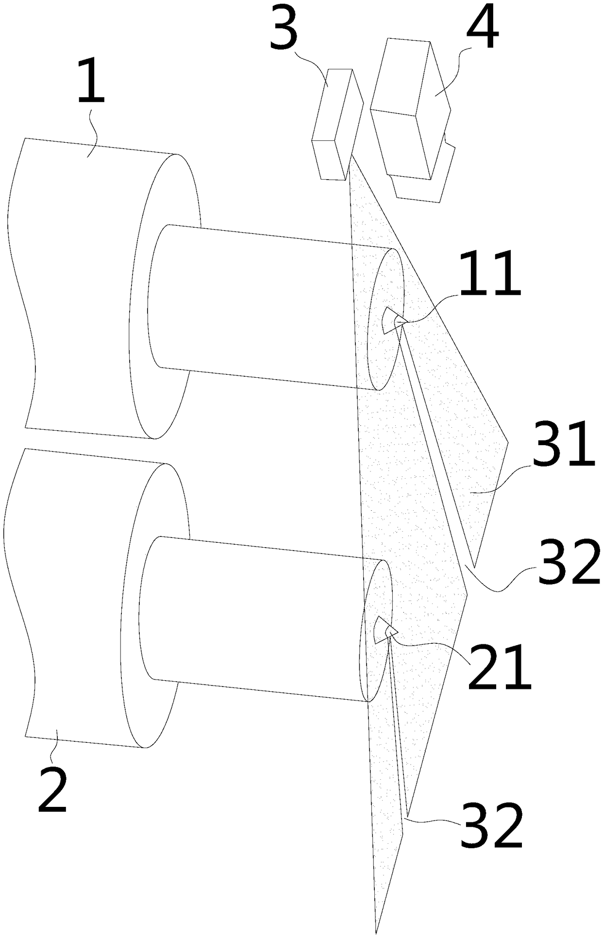
[0014] Such as figure 1 The roll position detection system of the rolling mill shown includes the upper roll 1 and the lower roll 2 to be detected, and includes a laser monitoring device. The upper roll 1 and the lower roll 2 are respectively provided with an upper roll cone 11 and a lower roll cone 11 at the same end. The roller cone 21, the light curtain 31 emitted by the laser monitoring device passes through the upper roller cone 11 and the lower roller cone 21 to form a light curtain shadow area 32. The laser monitoring device monitors the light curtain shadow area 32 and the light The change of the curtain 31 realizes the monitoring of the axial fluctuation of the upper roll 1 and the lower roll 2.

[0015] The invention uses the principle that the length of the laser line on the cone is changed when the roller moves in the bearing direction, and calculates the amount of movement...


PUM


Abstract

The invention relates to the field of steel rail rolling equipment, in particular to a system for position detection of rollers of a rolling mill. The system is capable of precisely realizing displacement monitoring of the rollers of the rolling mill according to an optical measurement principle and comprises a to-be-detected upper roller, a to-be-detected lower roller and a laser monitoring device. Same ends of the upper roller and the lower roller are provided with an upper roller cone and a lower roller cone respectively. A light curtain emitted by the laser monitoring device forms a light curtain shadow area after passing through the upper roller cone and the lower roller cone, and the laser monitoring device monitors the light curtain shadow area and light curtain changes to realize axial variation monitoring of the upper roller and the lower roller. By detection of the laser monitoring device, accurate displacement conditions of the upper roller and the lower roller are acquired, so that real-time accurate control can be realized to guarantee production smoothness. The system is especially suitable for production places which require accurate control of operating states of the upper roller and the lower roller in order to realize efficient production.

Description

Technical field [0001] The invention relates to the field of rail rolling equipment, in particular to a rolling mill roll position detection system. Background technique [0002] Due to the asymmetry of the shape of the rolled piece during the rolling process, there is axial movement of the rolls of the rolling mill. There is a large gap between the axial movement when the steel passes and when the steel is not steel. The axial movement detection conditions in the static state are good. Achieved through a simple method. However, it is difficult to measure the axial movement of the roll when it is affected by temperature, roll cooling water, dust, vibration, and large axial force. Without knowing the axial movement, the roll gap adjustment can only be carried out based on experience, resulting in defective products caused by a large number of adjustments. At the same time, the position of the upper and lower rolls will change when they pass through the steel. Due to the dynamic ...

Claims


Application Information

Patent Timeline
Patent Type & Authority Patents(China)
IPC IPC(8): B21B38/00B21B38/10
CPCB21B38/00B21B38/105B21B2269/12
Inventor 陶功明朱华林吴郭贤刘自彩
Owner PANGANG GRP PANZHIHUA STEEL & VANADIUM
Why Eureka
Try Eureka