
Glass drill machine tool

A glass and machine tool technology, applied in the field of glass drilling machine tools, can solve the problems of high scrap rate, easy breakage, poor manual drilling accuracy, etc., achieve low manufacturing cost and maintenance cost, prevent glass slag from splashing and hurt people, improve The effect of work efficiency

Inactive Publication Date: 2017-07-25
慈溪市隆诚贸易有限公司
View PDF9 Cites 5 Cited by
  • Summary
  • Abstract
  • Description
  • Claims
  • Application Information

AI Technical Summary

Problems solved by technology

[0002] With the advancement of science and technology, glass is no longer limited to the category of building materials, but has been applied to fields with higher technical content such as smartphone screens and TV screens. In order to realize product functions, it is often necessary to punch holes in the surface of the glass. Poor, easy to break, low efficiency, time-consuming and labor-intensive, while the special punching machine is expensive and has a high scrap rate, which cannot meet market demand

Method used


Image

  • Glass drill machine tool
  • Glass drill machine tool
  • Glass drill machine tool

Examples


Embodiment Construction

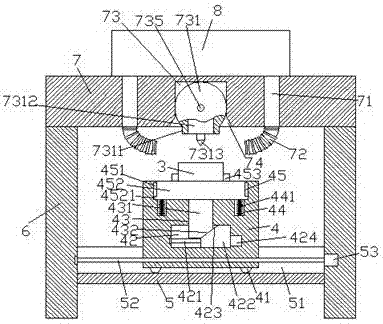
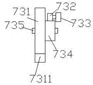
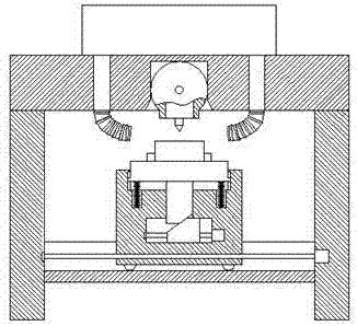
[0023] Such as Figure 1-Figure 5 As shown, a glass drilling machine tool of the present invention includes a horizontal rail 7 and uprights 6 fixed at the bottoms of both sides of the horizontal rail 7, and a chassis is fixed between the uprights 6 below the horizontal rail 7 5. The bottom frame 5 is provided with a first sliding groove 51, and a first screw rod 52 extending left and right is provided in the first sliding groove 51. The first screw rod 52 is screwed on The moving block 4 is connected in a form fit, the upper part of the moving block 4 is located outside the upper end surface of the bottom frame 5, the moving block 4 is provided with a sliding cavity 42 inside, and the upper end surface of the moving block 4 is provided with a receiving groove 45 Between the core position of the inner bottom surface of the receiving groove 45 and the core position of the upper end surface of the sliding cavity 42 is provided a channel groove 43 that penetrates the inside of the...


PUM


Abstract

The invention discloses a glass drill machine tool. The glass drill machine tool comprises a transverse fence and vertical pillars fixed to the bottoms of the two sides of the transverse fence, a bottom frame is fixedly arranged between the positions, below the transverse fence, of the vertical pillars, and a first sliding groove is formed in the bottom frame. A first spiral rod leftwards and rightwards extending is arranged in the first sliding groove, a movable block is connected to the first spiral rod in a spiral fit mode, and the upper portion of the movable block is located outside the upper end face of the bottom frame. A sliding cavity is formed in the movable block, a containing groove is formed in the upper end face of the movable block, and a passageway groove vertically penetrating through the interior of the movable block is formed between the key position of the bottom face of the containing groove and the key position of the upper end face in the sliding cavity. A second spiral rod leftwards and rightwards extending is arranged in the sliding cavity, a jacking sliding block is arranged on the second spiral rod, and a first oblique sliding face is arranged above the left side of the jacking sliding block. The glass drill machine tool is simple in structure and low in manufacturing and maintaining cost, lifting drill work can be automatically controlled, automatic angle adjusting of a drill bit is achieved, and the function that people are prevented from being hurt due to scattering of glass broken bits is further achieved.

Description

Technical field [0001] The invention relates to the technical field of glass drilling, in particular to a glass drilling machine tool. Background technique [0002] With the advancement of science and technology, glass has long been no longer limited to building materials, but has been applied to smart phone screens, TV screens and other fields with higher technical content. In order to achieve product functions, it is often necessary to punch holes on the glass surface with manual punching accuracy. Poor, easy to break, low efficiency, time-consuming and labor-intensive, while the special punching machine is expensive and has a high scrap rate, which cannot meet market demand. Summary of the invention [0003] The technical problem to be solved by the present invention is to provide a glass drilling machine tool, which can solve the above-mentioned problems in the current technology. [0004] The present invention is achieved through the following technical solutions: a glass dril...

Claims


Application Information

Patent Timeline
IPC IPC(8): B28D1/14B28D7/00B28D7/02
CPCB28D1/14B28D7/00B28D7/02
Inventor 程佩芳
Owner 慈溪市隆诚贸易有限公司
Learn More