Motion based stripping dry adhesion mechanism and implementation method

A realization method and technology of dry adhesion, which is applied in the field of bionic dry adhesion, can solve the problems of dry adhesion surface structure damage, increase external force, weaken the gripping strength of mechanism adhesion, etc., achieve high-efficiency movement peeling, and the principle is simple and reliable , cost reduction effect

Active Publication Date: 2017-07-25
XI AN JIAOTONG UNIV
View PDF7 Cites 4 Cited by
  • Summary
  • Abstract
  • Description
  • Claims
  • Application Information

AI Technical Summary

Problems solved by technology

Although many designs can achieve strong gripping force for dry adhesion, there are still many deficiencies in how to effectively release the grasped objects: some designs require external field-assisted desorption (electric field-assisted desorption, vacuum-assisted desorption) desorption), which will increase the complexity of the design of the desorption system and unnecessary energy loss; some increase the external force and force the desorption, which will cause structural damage to the dry adhesion surface, and it is difficult to realize the desorption of light and small objects. Effective release; some use asymmetric dry-adhesive microscopic surfaces to achieve good detachment design, but this will greatly weaken the adhesion grip strength of the mechanism

Method used


Image

  • Motion based stripping dry adhesion mechanism and implementation method
  • Motion based stripping dry adhesion mechanism and implementation method
  • Motion based stripping dry adhesion mechanism and implementation method

Examples


Embodiment Construction

[0017] The present invention will be described in detail below in combination with schematic diagrams.

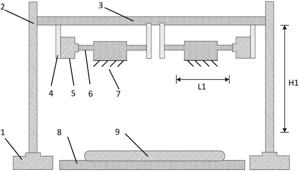
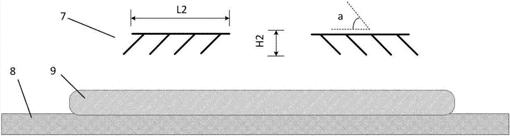
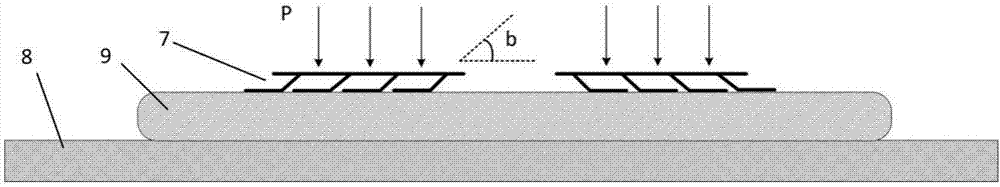
[0018] Such as figure 1 As shown, a dry adhesion mechanism based on motion peeling includes two dry adhesion structures 7 composed of inclined sheet structures. side, each dry adhesion structure 7 is installed on the slider of the horizontal ball screw 6, and the horizontal ball screw 6 is driven by the horizontal motor 5 to realize the horizontal left and right movement of the dry adhesion structure 7; the horizontal motor 5 is connected by the bracket 4 On the beam 3, both ends of the beam 3 are installed on the sliders of the vertical ball screw 2, and the vertical ball screw 2 is driven by the vertical motor 1, and the vertical movement of the beam 3 can be realized under the drive of the vertical motor 1; The adhered object 9 is placed on the horizontal platform 8 below the attached structure 7 , the movement stroke of the mechanism in the vertical direction is H1, an...


PUM


Abstract

The invention discloses a motion based stripping dry adhesion mechanism and an implementation method. The mechanism comprises two dry adhesion structures which are each formed by an inclined flaky structure. The inclination directions of the two dry adhesion structures are opposite, and the two dry adhesion structures are arranged symmetrically. Each dry adhesion structure is mounted on a sliding block of a horizontal ball screw, each horizontal ball screw is driven by a horizontal motor, and horizontal left-and-right motion of each dry adhesion structure is achieved. The horizontal motors are connected to a cross beam through supports. The two ends of the cross beam are mounted on sliding blocks of vertical ball screws, each vertical ball screw is driven by a vertical motor, and vertical up-and-down motion of the cross beam can be achieved under drive of the vertical motors. An adhered object is put on a horizontal platform below the dry adhesion structures. When the two dry adhesion structures are controlled to horizontally move in the inclination directions, object adhesion grabbing is achieved. When the two dry adhesion structures are controlled to horizontally move in the directions opposite to inclination directions, efficient and fast stripping and releasing of the adhered object are achieved. The motion based stripping dry adhesion mechanism can be widely used for the field of dry adhesion of belt conveyors, mechanical arms, micro suction cups and the like.

Description

technical field [0001] The invention belongs to the technical field of bionic dry adhesion, and in particular relates to a dry adhesion mechanism based on motion stripping and a realization method. Background technique [0002] At present, the common adhesion methods mainly include: traditional vacuum adsorption, mechanical meshing, electromagnetic adsorption, dry adhesion, wet adhesion and other adhesion methods. Compared with traditional vacuum adsorption, mechanical meshing, electromagnetic adsorption and other adhesion methods, dry adhesion has the advantages of miniaturization, flexibility, and less dependence on the shape of the surface to be adhered, and is suitable for integration into intelligent control and operation applications At the same time, dry adhesion will not cause damage and pollution to the surface of the contact object, and can work in a vacuum environment. Therefore, this kind of adhesion has great potential in bionic wall-climbing robots, space envir...

Claims


Application Information

Patent Timeline
Patent Type & Authority Applications(China)
IPC IPC(8): B65G47/90
CPCB65G47/901
Inventor 邵金友王月田洪淼李祥明王春慧胡鸿
Owner XI AN JIAOTONG UNIV
Why Eureka
Try Eureka