Overlapped-type zero-leakage hydraulic lock valve

A zero-leakage, hydraulic lock technology, applied in the direction of fluid pressure actuators, servo motor components, mechanical equipment, etc., can solve the problem of increased volume of valve blocks installed in superimposed valves, heavy processing workload, leakage of superimposed hydraulic lock valves, etc. problems, to achieve the effect of convenient and standardized design, material saving, and no offset position maintenance

Inactive Publication Date: 2017-07-25
CHINA NAT HEAVY MACHINERY RES INSTCO
View PDF5 Cites 2 Cited by
  • Summary
  • Abstract
  • Description
  • Claims
  • Application Information

AI Technical Summary

Problems solved by technology

[0003] The purpose of the present invention is to overcome the leakage of the existing superimposed hydraulic lock valve, and the problems caused by the increase in the volume of the valve block installed in the superimposed valve and the heavy workload of design and processing when zero leakage is required.

Method used


Image

  • Overlapped-type zero-leakage hydraulic lock valve
  • Overlapped-type zero-leakage hydraulic lock valve
  • Overlapped-type zero-leakage hydraulic lock valve

Examples


Embodiment 1

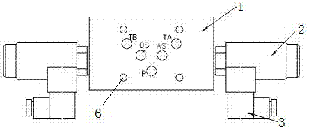
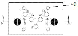
[0019] The existing stack valve is installed on the stack valve block. In order to achieve zero leakage, another valve hole needs to be designed on the stack valve block to install the plug-in zero-leakage hydraulic lock valve, but this design leads to the processing of the stack valve block. The workload is large, the volume is large, and it is not convenient for standardized design. In order to solve the above problems, this embodiment provides a superimposed zero-leakage hydraulic lock valve, such as figure 1 As shown, including the installation valve block 1, the installation valve block 1 has six surfaces, and a pair of opposite surfaces are vertically provided with a cartridge valve hole, respectively, the first cartridge valve hole CA and the second cartridge valve hole CB, Two plug-in valve holes are arranged opposite to each other, and a plug-in zero-leakage hydraulic lock valve 2 is inserted in CA and CB respectively, and each plug-in zero-leakage hydraulic lock valve...

Embodiment 2

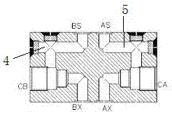
[0025] On the basis of Example 1, such as image 3 As shown, the third port and the fourth port of the first cross hole 4 and the third port and the fourth port of the second cross hole 5 are all equipped with oil plugs. The above-mentioned ports are for the convenience of opening two cross holes for technical considerations, while the oil plug is used for isolation. The use of the oil plug not only solves the problem of the process, but also blocks all port to prevent oil leakage.

Embodiment 3

[0027] On the basis of Example 1, it needs to be further explained that the choice of material determines the pressure resistance level of the valve block, and at the same time the choice of material determines the manufacturing cost of the valve block. Under the condition of meeting the pressure requirements, try to use low-cost In order to save costs, the following principles are generally followed: when the working pressure P<6.3MPa on the installation valve block 1, the installation valve block 1 is made of cast iron HT20-40. When the working pressure of the installed valve block 1 is 6.3MPa≤P<21MPa, the installed valve block 1 is made of aluminum alloy forging or No. 20 forged steel or Q235; when the working pressure of the installed valve block 1 is P≥21MPa, The installation valve block 1 is made of No. 35 forged steel.

[0028] The superimposed zero-leakage hydraulic lock valve provided by the present invention includes a plug-in zero-leakage hydraulic lock valve and an...


PUM


Abstract

The invention provides an overlapped-type zero-leakage hydraulic lock valve which comprises inserted type zero-leakage hydraulic lock valves and an installation valve block. The installation valve block is provided with six faces, one pair of opposite faces are each vertically provided with an inserted valve hole, the two inserted valve holes are oppositely formed, the inserted zero-leakage hydraulic lock valves are inserted into the first inserted valve hole and the second inserted valve hole correspondingly, and each inserted zero-leakage hydraulic lock valve is connected with an electric plug. The overlapped-type zero-leakage hydraulic lock valve can reduce the design and machining work amount, save materials and achieve standard design conveniently as an ordinary overlapped-type hydraulic lock valve; and meanwhile, the overlapped-type zero-leakage hydraulic lock valve furthermore has a zero-leakage function, and an execution element which is required to work at any position in a travel range can achieve non-deviation position maintenance.

Description

technical field [0001] The invention belongs to the technical field of fluid control and control, and in particular relates to a superimposed zero-leakage hydraulic lock valve. Background technique [0002] In engineering projects, many actions of mechanical equipment are realized by controlling actuators through hydraulic circuits. In the hydraulic circuit, because the superimposed valve can reduce the design and processing workload, save materials and realize the standardized design conveniently, many hydraulic circuits are realized through the superimposed valve. For the actuator that needs to work at any position within the stroke range, a superimposed hydraulic lock valve is required to lock the position of the actuator in the superimposed valve, but the superimposed hydraulic lock valve has certain leakage due to the structure, so for The use of actuators with strict requirements that do not allow offset, the circuit will use a plug-in zero-leakage hydraulic lock valv...

Claims


Application Information

Patent Timeline
Patent Type & Authority Applications(China)
IPC IPC(8): F15B13/02
CPCF15B13/02
Inventor 魏志毅魏维刚尤磊
Owner CHINA NAT HEAVY MACHINERY RES INSTCO
Why Eureka
Try Eureka