Buffer type traction machine band-type braking device

A braking device and traction machine technology, applied in the direction of drum brakes, brake types, brake actuators, etc., can solve problems such as negative impact of equipment, harsh braking noise, etc., and achieve the goal of reducing instantaneous impact and improving comfort Effect

Pending Publication Date: 2017-07-25
苏州蒙特纳利驱动设备有限公司
View PDF5 Cites 1 Cited by
  • Summary
  • Abstract
  • Description
  • Claims
  • Application Information

AI Technical Summary

Problems solved by technology

In the prior art, after the power is cut off, the brake spring assembly intervenes too quickly, causing the brake shoe on the brake arm to quickly cling to the main shaft of the traction machine, which easily leads to loud and harsh braking noise, and at the same time, the passengers in the car There will be greater discomfort due to excessive braking, and rapid braking will have a negative impact on the equipment itself

Method used


Image

  • Buffer type traction machine band-type braking device
  • Buffer type traction machine band-type braking device

Examples


Embodiment Construction

[0020] The present invention will now be further described in detail in conjunction with the accompanying drawings and embodiments. These drawings are all simplified schematic diagrams, only illustrating the basic structure of the present invention in a schematic manner, so it only shows the composition related to the present invention.

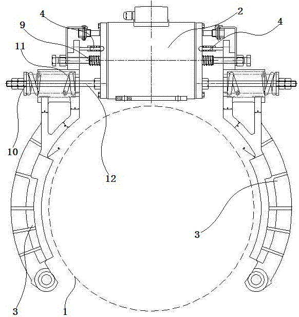
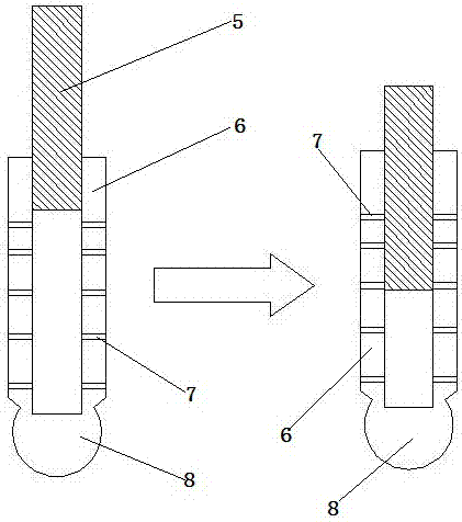
[0021] Such as figure 1 and figure 2 As shown in , a buffer brake device for a traction machine includes: two brake arms surrounding the main shaft of the traction machine, and a brake connected to the two brake arms at the same time, and each brake arm is connected to one end of the brake All are equipped with an electromagnetic ejector rod, a brake spring assembly and a piston buffer; the piston buffer includes a plug rod and a plug tube sleeved together. There are several through holes on the side wall of the plug tube, and the free end of the plug rod is connected to the brake. The free end of the arm and the plunger is connected to the...


PUM


Abstract

The invention discloses a buffer type traction machine band-type braking device which comprises two band-type arms surrounding a traction machine spindle, and a brake connected with the both band-type arms. An electromagnetic ejecting rod, a brake spring set and a piston buffer are arranged at the end, connected with the brake, of each band-type arm. Each piston buffer comprises a piston rod sleeved with a piston cylinder and the piston cylinder. A plurality of through holes are formed in the side wall of each piston cylinder. The free end of each piston rod is connected with the corresponding band-type arm. The free end of each piston cylinder is connected with the brake through a ball. Since the first end of each band-type arm is provided with the piston buffer, the period from the time when the band-type arms start braking to the time when the braking force reaches a maximum value can be appropriately prolonged through the piston buffers, braking is effectively controlled while the braking effect is not affected, the comfort of a rider can be improved, and temporary impact of braking to equipment is reduced.

Description

technical field [0001] The invention relates to a brake, in particular to a buffer type traction machine brake device. Background technique [0002] At present, domestic elevators drive the drum brake arm of the traction machine. In the energized state, the electromagnet pushes one end of the brake arm away from the main shaft of the traction machine through the ejector rod. At this time, the main shaft of the traction machine can rotate freely; In the power state, the ground magnet loses power and loses its force on the brake arm. At this time, the brake spring pushes the same end of the brake arm against the main shaft of the traction machine to achieve braking. In the prior art, after the power is cut off, the brake spring assembly intervenes too quickly, causing the brake shoe on the brake arm to quickly cling to the main shaft of the traction machine, which easily leads to loud and harsh braking noise, and at the same time, the passengers in the car There will be great...

Claims


Application Information

Patent Timeline
Patent Type & Authority Applications(China)
IPC IPC(8): F16D51/20F16D65/22B66B11/04F16D121/22
CPCF16D51/20F16D65/22B66B11/04F16D2051/001F16D2121/22
Inventor 符斌余勇虎赵健
Owner 苏州蒙特纳利驱动设备有限公司
Why Eureka
Try Eureka