
Method for detecting stem portion precision of valve stem

A technology of precision detection and valve stem, applied in the direction of mechanical roughness/irregularity measurement, measuring device, mechanical measuring device, etc., can solve problems such as difficult to meet product quality requirements, increase production cost, increase product error rate, etc., to achieve Accurate and reliable test results, improve product accuracy, and improve product quality

Inactive Publication Date: 2017-07-25
YANGTZE NORMAL UNIVERSITY
View PDF2 Cites 5 Cited by
  • Summary
  • Abstract
  • Description
  • Claims
  • Application Information

AI Technical Summary

Problems solved by technology

[0004] The processing accuracy and structure of the valve play a decisive role in the movement of the engine valve train. At the same time, the valve rod is the key part of the valve. It is not only the design standard, but also the process and inspection standard. It is closely related to almost all parts of the valve. relationship, the traditional valve stem detection method needs to rely on a lot of labor to complete, the detection cost is high and the efficiency is low, and the relevant inspection tools for quality and accuracy detection are easily affected by the factors of the operator, and it is easy to cause detection due to human visual fatigue. The instability of the product increases the error rate of the product
Difficulty in meeting ever-increasing product quality requirements
[0005] Whether the end face of the valve stem is flat or not is one of the important factors affecting the assembly accuracy of the valve. Existing manufacturers mainly use an end face runout instrument to detect the runout of the end face of the rod, which has defects such as large equipment, high cost, and large occupied space. Seriously increased the production cost of the enterprise

Method used


Image

  • Method for detecting stem portion precision of valve stem
  • Method for detecting stem portion precision of valve stem
  • Method for detecting stem portion precision of valve stem

Examples


Embodiment

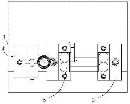
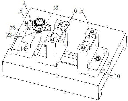
[0045] A method for detecting the accuracy of the stem portion of a valve stem, including the step of detecting the flatness of the end surface of the stem portion of the valve stem. The two sides of the lower part of the circumferential surface of the rod contact to realize the support positioning, and the end face of the rod is used to limit the contact of the end face of the rod, and then the measuring head of the lever dial gauge is used to contact the end face of the valve rod after positioning, and then rotate The valve realizes the detection of the flatness of the end surface of the valve stem; the support member on the peripheral surface of the stem is obtained by using equal and horizontally arranged paired spheres.

[0046] In this way, the method includes the step of detecting the flatness of the end surface of the valve stem part, and wherein the horizontally paired spheres are used to support the valve stem part, so that when the rotation is detected, the stem part...


PUM


Abstract

The invention discloses a method for detecting the stem portion precision of a valve stem. The method comprises a step of detecting the flatness of the stem portion end face of the valve stem and is characterized in that when the flatness of the stem portion end face of the valve stem is detected, a stem portion circumferential surface support member is in contact with both sides of the lower side of the circumferential surface of the valve stem portion in a horizontal state to achieve supporting and positioning, a stem portion end face stopping member is abutted against the stem portion end face so as to stop the stem portion end face, the probe of a dial test indicator is in contact with the positioned stem portion end face of the valve stem, a valve is rotated to detect the flatness of the stem portion end face of the valve stem; and the stem portion circumferential surface support member comprises identical and horizontally paired balls. The method is easy to implement, low in cost, and convenient to operate, can detect the flatness of the stem portion end face of the valve stem and the run-out tolerance of the stem portion of the valve stem, and is accurate and reliable in and detection result, and beneficial to improvement in product precision.

Description

technical field [0001] The invention relates to the technical field of production detection of automobile engine parts, in particular to a method for detecting the accuracy of a valve stem. Background technique [0002] The automobile engine can convert the chemical energy of fuel or other forms of energy into mechanical energy to provide power for the automobile. It is the heart of the automobile and belongs to a technology-intensive product. With the development of our country's economy, while the demand for automobiles is increasing day by day, the automobile industry has developed rapidly, and people's requirements for the performance of automobile engines are also getting higher and higher. [0003] In an automobile engine, the intake and exhaust valve is a component composed of a disc part and a rod part coaxial with the disc part. It is one of the key parts of the car engine and is the door of the engine combustion chamber. The key basic parts that seal the intake an...

Claims


Application Information

Patent Timeline
Patent Type & Authority Applications(China)
IPC IPC(8): G01B5/28G01B5/00
CPCG01B5/28G01B5/003
Inventor 张军何仁琪
Owner YANGTZE NORMAL UNIVERSITY
Learn More