Permanent-magnet bias no-bearing switch reluctance starter/generator

A technology of switched reluctance and permanent magnet bias, applied in the direction of magnetic circuit shape/style/structure, magnetic circuit, synchronous machine, etc., can solve problems such as slot full rate limitation

Active Publication Date: 2017-07-25
BEIHANG UNIV +1
View PDF4 Cites 15 Cited by
  • Summary
  • Abstract
  • Description
  • Claims
  • Application Information

AI Technical Summary

Problems solved by technology

Although the electromagnetic torque of the motor can be increased to a certain extent by adjusting the position of the stator torque core teeth, the degree of increase is limited due to the limitation of the slot full rate

Method used


Image

  • Permanent-magnet bias no-bearing switch reluctance starter/generator
  • Permanent-magnet bias no-bearing switch reluctance starter/generator
  • Permanent-magnet bias no-bearing switch reluctance starter/generator

Examples


Embodiment Construction

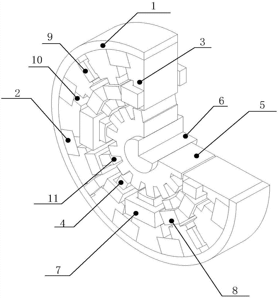
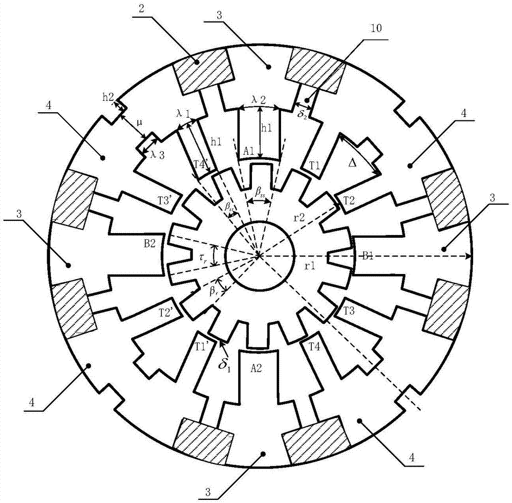
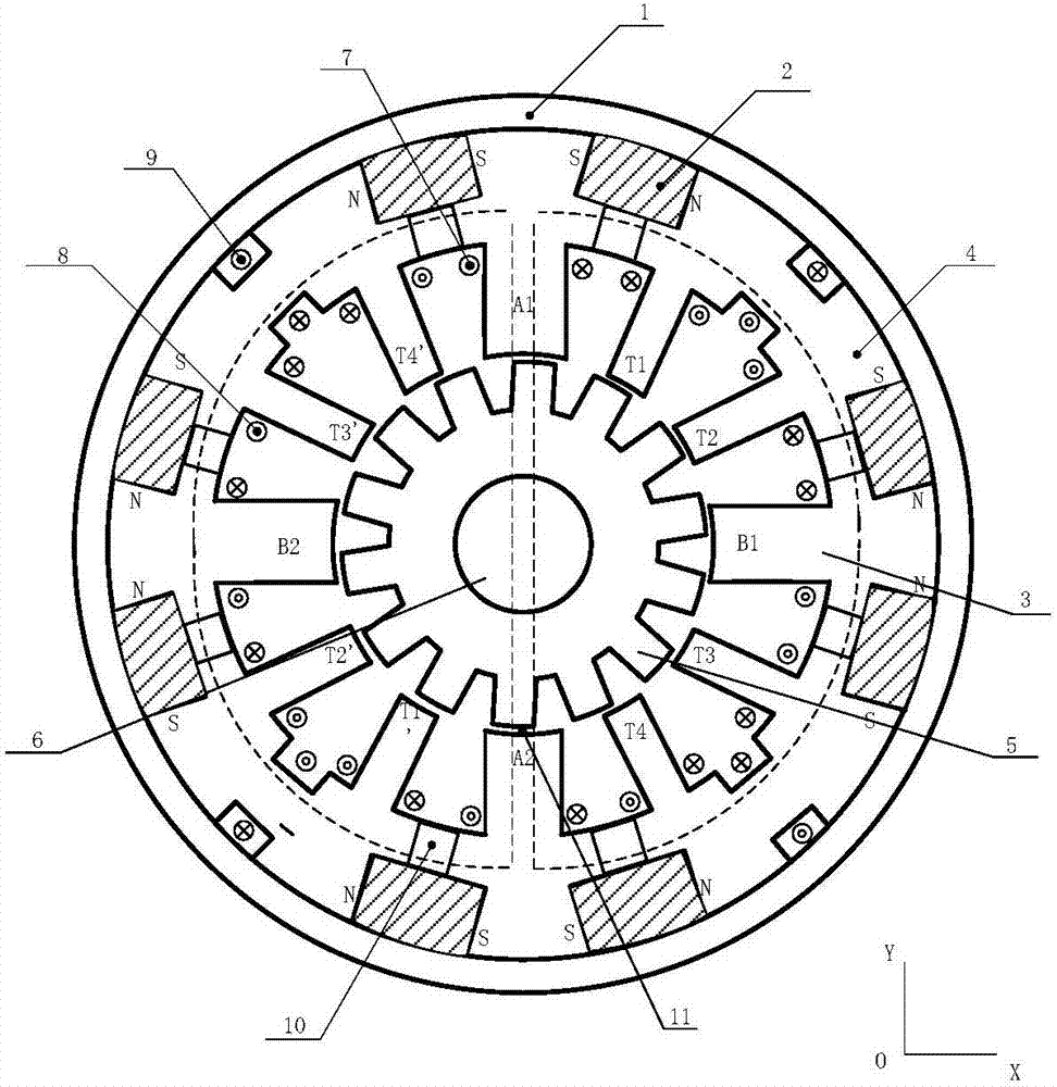
[0015] like figure 1As shown, it is an axial sectional view of a permanent magnet biased bearingless switched reluctance starter / generator of the present invention, which consists of a stator back yoke 1, eight permanent magnets 2, four stator suspension force iron cores 3, four The stator torque core 4 , a rotor core 5 , a shaft 6 , four suspension force winding coils 7 , eight torque winding coils 8 , and four auxiliary excitation winding coils 9 are composed. The stator suspension force iron core 3 is composed of four stator suspension force iron core teeth placed along the +x, -x, +y, -y directions, and the suspension force winding coil 7 is wound thereon; the stator torque iron core 4 has a total of eight teeth, It is evenly distributed on the circumference, and the torque winding coil 8 is wound thereon. Set the outer diameter of the sub-suspended force core 3 and the stator torque core 4 as r1, the inner diameter as r2, and the arc length of the tooth root of the stat...


PUM


Abstract

The invention discloses a permanent-magnet bias no-bearing switch reluctance starter/generator, and the starter/generator consists of a stator back yoke, permanent magnets, stator suspension force iron cores, stator torque iron cores, a rotor core, suspension force winding coils, torque winding coils, auxiliary excitation winding coils, and a shaft. The inner side of the stator back yoke is provided with the stator suspension force iron cores and the stator torque iron cores, and the permanent magnets are embedded into the stator back yoke between the stator suspension force iron cores and the stator torque iron cores. The stator suspension force iron cores and the stator torque iron cores are respectively provided with the suspension force winding coils and the torque winding coils in a winding manner. The auxiliary excitation winding coils are wound in auxiliary winding installation grooves at yoke parts of the stator torque iron cores. The rotor core is disposed in the stator suspension force iron cores and the stator torque iron cores, and the interior of the rotor core is provided with the shaft. The permanent magnets are used for providing a bias magnetic field, thereby reducing the motor loss and shortening the axial length. Meanwhile, the permanent magnets and the auxiliary excitation winding coils are used for providing exciting flux, thereby increasing the electromagnetic torque of the motor, and improving the efficiency of the motor.

Description

technical field [0001] The invention relates to a 12 / 14 bearingless switched reluctance motor with permanent magnet auxiliary excitation, in particular to a permanent magnet biased bearingless switched reluctance starter / generator, which can be used as a high-speed and high-precision drive motor. Background technique [0002] The switched reluctance motor is a new type of speed-regulating motor with a simple structure that has been gradually developed by the continuous progress of modern microelectronics technology, modern power electronics technology and control technology in the past two decades. Its operating principle is different from that of induction motors and DC. Instead, it relies on the "principle of minimum reluctance" to generate torque. The stator and rotor of the switched reluctance motor are of double salient pole structure, which can be formed by laminating silicon steel sheets. The stator tooth poles are wound with concentrated windings, and the rotor has n...

Claims


Application Information

Patent Timeline
Patent Type & Authority Applications(China)
IPC IPC(8): H02K21/44H02K21/04H02K1/14H02K1/17
CPCH02K1/145H02K1/17H02K21/04H02K21/44H02K2213/03
Inventor 王惠军庞明琪曲政魏新生张明举
Owner BEIHANG UNIV
Why Eureka
Try Eureka