Automatic rivet removal tool

A rivet and tooling technology, applied in the field of automatic rivet dismantling tooling, can solve the problems of iron filing operator injury, high work intensity, low work efficiency, etc., and achieve the effects of improving disassembly convenience, improving continuous workability, and increasing processing efficiency.

Inactive Publication Date: 2017-07-28
ZHEJIANG DEREBAO ELECTRIC TECH
View PDF13 Cites 2 Cited by
  • Summary
  • Abstract
  • Description
  • Claims
  • Application Information

AI Technical Summary

Problems solved by technology

[0002] At present, the connection of two workpieces is usually connected by rivets, and riveting errors often occur in the process of processing, which requires disassembly of the rivets. However, the existing rivet disassembly methods include electric drill disassembly, manual disassembly The rivets are disassembled or disassembled by impact. The disassembly by electric drill is easy to damage the workpiece, and the iron filings generated by electric drill disassembly are likely to cause physical injury to the operator, while the work efficiency of manual disassembly is lower. It is very low, which is not conducive to quick disassembly, and the work intensity is high. Although the impact disassembly method can be disassembled quickly, the disassembled rivets are easily attached to the punch, which is not conducive to the operator's multiple disassembly operations and affects the operator's rivets. Batch disassembly work
[0003] For example, the published patent application number "201310470671.X", the patent name "a rivet removal method and its removal device", which is to impact the rivet with a punch, so that the rivet is punched into the blanking hole in the mold base, and the alignment is completed. The removal of rivets, but in the process of dismantling the rivets by the punch for many times, the rivet is easily attached to the punch due to the impact of the punch, which is not conducive to the operator to use the punch to dismantle the rivet for many times. Affect the convenience of the operator

Method used


Image

  • Automatic rivet removal tool
  • Automatic rivet removal tool
  • Automatic rivet removal tool

Examples


Embodiment Construction

[0027] The preferred embodiments of the present invention will be described in detail below in conjunction with the accompanying drawings, so that the advantages and features of the present invention can be more easily understood by those skilled in the art, so as to define the protection scope of the present invention more clearly.

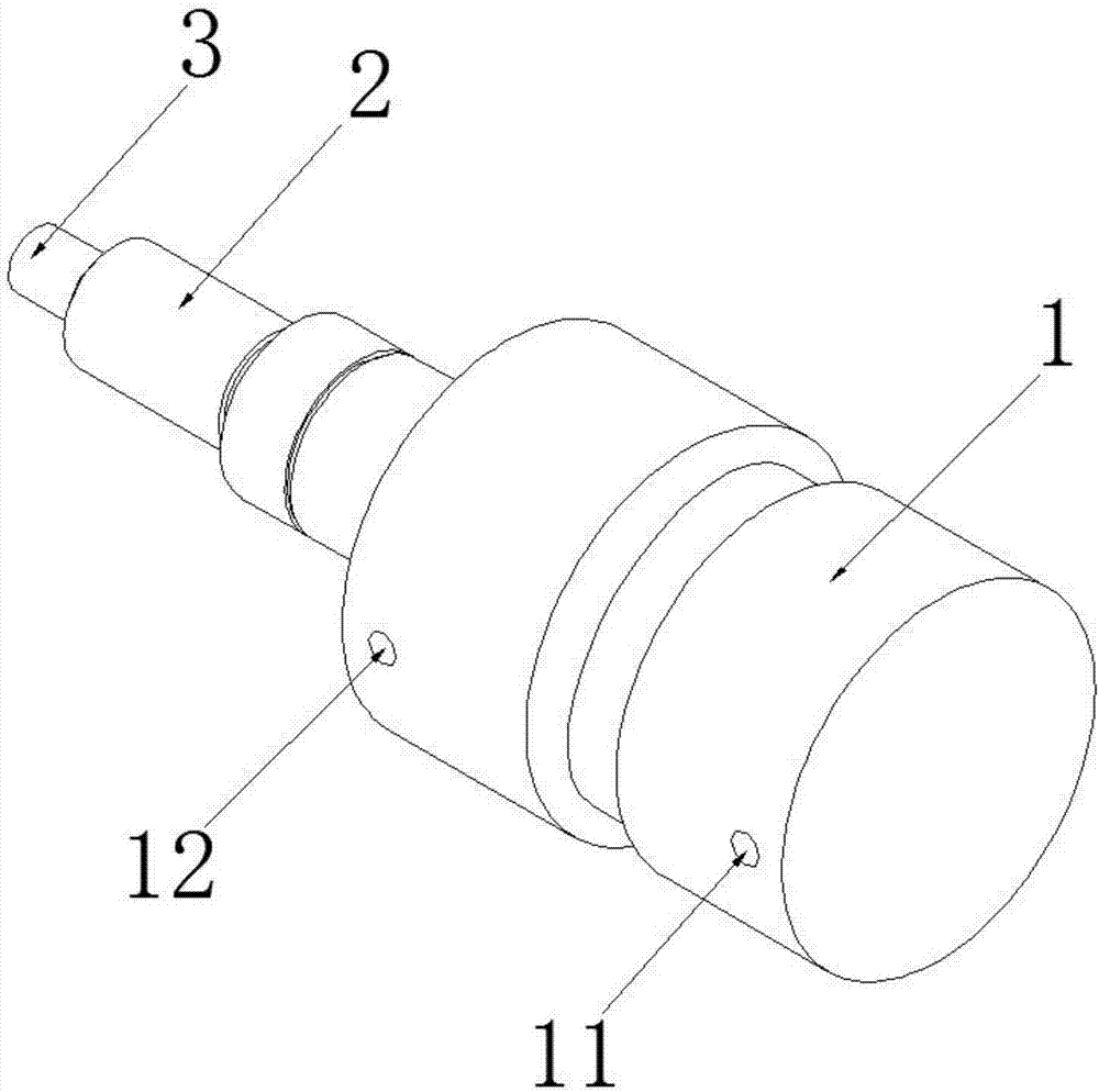
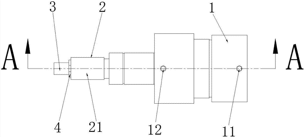
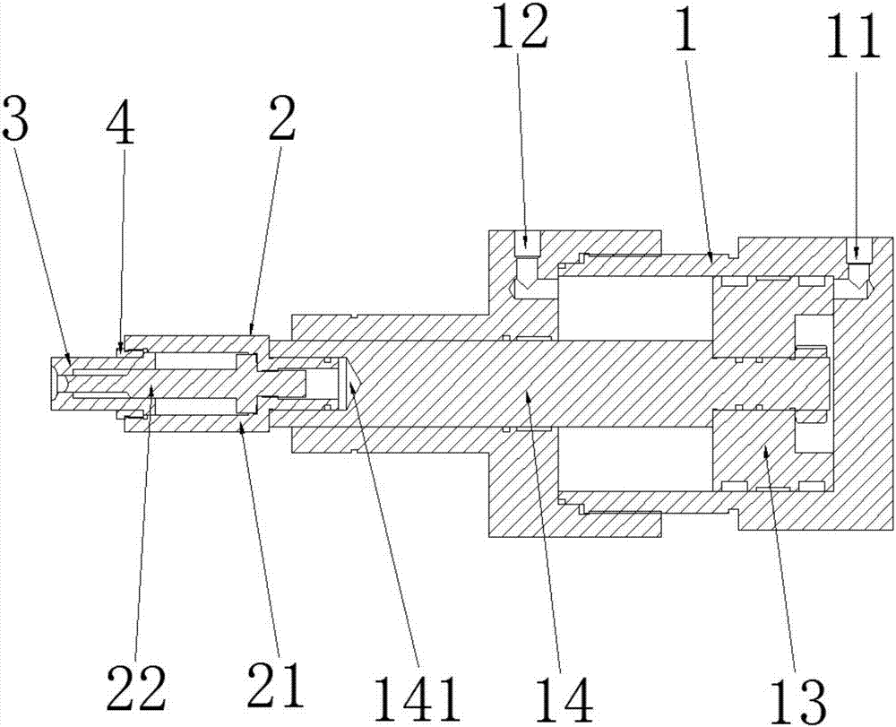
[0028] like figure 1 and Figure 12 The shown automatic rivet removal tooling includes a riveting seat 2, and the riveting seat 2 includes a punch seat 21, a punch 22 arranged in the punch seat 21, a dismantling head 3 sleeved on the punch 22 and Be connected with the ferrule 4 that is connected on the punch seat 21 and prevent that the head 3 is detached from the punch seat 21. The second arc-shaped groove 33 is matched with the first arc-shaped groove 220 , and the curvature of the second arc-shaped groove 33 and the first arc-shaped groove 220 are equal.

[0029] The inside of the punch seat 21 is provided with a seat hole 212, a large threa...


PUM


Abstract

The invention discloses an automatic rivet removal tool which comprises a rivet removal base (2). The rivet removal base (2) comprises a punch base (21), a punch (22), a removal head (3) and a clamping sleeve (4), wherein the punch (22) is arranged in the punch base (21), the punch (22) is sleeved with the removal head (3), and the clamping sleeve (4) is connected to the punch base (21) and prevents the removal head (3) from being disengaged from the punch base (21). The ends, stretching out of the punch base (21), of the removal head (3) and punch (22) are provided with a second arc groove (33) and a first arc groove (220) which are matched with the outer surface of a rivet head of a rivet correspondingly. The bending radian of the second arc groove (33) is equal to that of the first arc groove (220). By means of the rivet removal tool, rivets on workpieces can be removed, the removed rivets can be prevented from being attached to the exterior of the removal tool, operators can remove rivets repeatedly and conveniently, and production efficiency of the operators is effectively improved.

Description

technical field [0001] The invention relates to an automatic rivet removal tool. Background technique [0002] At present, the connection of two workpieces is usually connected by rivets, and riveting errors often occur in the process of processing, which requires disassembly of the rivets. However, the existing rivet disassembly methods include electric drill disassembly, manual disassembly The rivets are disassembled or disassembled by impact. The disassembly by electric drill is easy to damage the workpiece, and the iron filings generated by electric drill disassembly are likely to cause physical injury to the operator, while the work efficiency of manual disassembly is lower. It is very low, which is not conducive to quick disassembly, and the work intensity is high. Although the impact disassembly method can be disassembled quickly, the disassembled rivets are easily attached to the punch, which is not conducive to the operator's multiple disassembly operations and affe...

Claims


Application Information

Patent Timeline
Patent Type & Authority Applications(China)
IPC IPC(8): B21J15/50
CPCB21J15/50
Inventor 杨春炜余志军
Owner ZHEJIANG DEREBAO ELECTRIC TECH
Why Eureka
Try Eureka