
Cutting mechanism for steel cutting device and convenient to detach and maintain

A cutting mechanism and cutting device technology, which are applied in the directions of the cutter of the sawing machine, the sawing machine, the attachment of the sawing machine, etc., can solve the problems of inconvenience and the like, and achieve the effect of convenient transportation and installation.

Active Publication Date: 2017-07-28
迁安市大成彩钢有限公司
View PDF6 Cites 2 Cited by
  • Summary
  • Abstract
  • Description
  • Claims
  • Application Information

AI Technical Summary

Problems solved by technology

[0002] The role of the steel cutting machine is to cut steel. The steel cutting machines in the prior art are all fixed and installed in one piece, which is very inconvenient in the process of transportation or maintenance.

Method used


Image

  • Cutting mechanism for steel cutting device and convenient to detach and maintain
  • Cutting mechanism for steel cutting device and convenient to detach and maintain
  • Cutting mechanism for steel cutting device and convenient to detach and maintain

Examples


Embodiment Construction

[0026] The technical solutions in the embodiments of the present invention will be clearly and completely described below in conjunction with the accompanying drawings in the embodiments of the present invention. Obviously, the described embodiments are only part of the embodiments of the present invention, not all of them. Based on the embodiments of the present invention, other embodiments obtained by persons of ordinary skill in the art without making creative efforts all belong to the protection scope of the present invention.

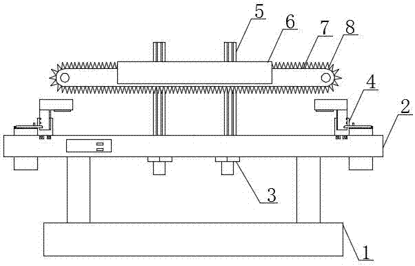
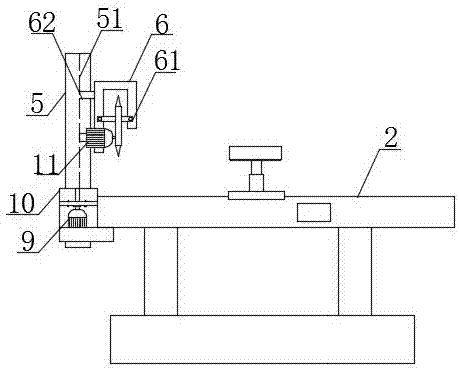
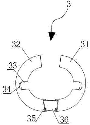
[0027] see Figure 1-6 , the present invention provides a technical solution: a cutting mechanism for a steel cutting device that is easy to disassemble and maintain, including a cutting device base 1, the upper end surface of the cutting device base 1 is fixedly connected with a cutting platform 2 through symmetrically arranged support columns, The MAM-200 controller is installed on the cutting platform 2, and the MAM-200 controller is electricall...


PUM


Abstract

The invention provides a cutting mechanism for a steel cutting device and convenient to detach and maintain. The cutting mechanism comprises a cutting device base, the upper end face of the cutting device base is fixedly connected with a cutting platform through supporting pillars which are symmetrically arranged, the cutting platform is provided with an MAM-200 controller, and the MAM-200 controller is electrically connected with a power source; and the two ends, close to the edge, of the cutting platform are symmetrically and detachably provided with steel clamping devices, two sets of electric sliding channels driven by brushless direct-current servo motors are arranged between the two sets of steel clamping devices in the manner of being symmetrical about the center line of the cutting platform, the brushless direct-current servo motors are electrically connected with the MAM-200 controller, and the lower segments of the electric sliding channels are detachably installed on the cutting platform through electric sliding channel fixing pieces. All key cutting mechanism bodies and cutting-assisted mechanisms can be steadily connected with or safely detached from the cutting device, and the effect that detaching, transport and installation are all convenient to perform is achieved.

Description

technical field [0001] The invention relates to the technical field of steel material cutting, in particular to a cutting mechanism for a steel material cutting device that is easy to disassemble and maintain. Background technique [0002] The role of the steel cutting machine is to be used for cutting steel. The steel cutting machines in the prior art are all integrated and fixedly installed, which is very inconvenient in the process of transportation or maintenance. A detachable cutting mechanism on the cutting machine is proposed so as to achieve fast, accurate and convenient use during transportation and maintenance. Contents of the invention [0003] The object of the present invention is to provide a cutting mechanism for a steel cutting device that is easy to disassemble and maintain, so as to achieve fast, accurate and convenient use effects during transportation and maintenance. [0004] In order to achieve the above object, the present invention provides the fol...

Claims


Application Information

Patent Timeline
IPC IPC(8): B23D55/00B23D55/04
CPCB23D55/00B23D55/04B23D57/02B23D59/00B23D61/00
Inventor 孙立民国际昌
Owner 迁安市大成彩钢有限公司
Learn More