Al technical title is built by PatSnap Al team. It summarizes the technical point description of the patent document.
The technology of a cutting device and an offset printing machine, which is applied in metal processing and other directions, can solve the problems of increasing the cost of cutting, high labor intensity of workers, and reducing cutting efficiency, etc., and achieve the effect of extending the service life, reducing labor intensity and improving efficiency.
Active Publication Date: 2017-07-28
MILLENNIUM PRINTING SHENZHEN CO LTD
View PDF6 Cites 8 Cited by
Summary
Abstract
Description
Claims
Application Information
AI Technical Summary
This helps you quickly interpret patents by identifying the three key elements:
Problems solved by technology
Method used
Benefits of technology
Problems solved by technology
[0005] In order to overcome the manual cutting of long paper, the present invention needs to measure the paper first and then cut the paper. The labor intensity of the workers is high, and the cutting efficiency will be reduced. However, the manufacturing cost of the cutting machine is high, and it will be difficult to use the cutting machine to cut the paper. The shortcoming of increasing the cost of cutting and the long white paper stored in the warehouse is easy to be scattered. The technical problem to be solved by the present invention is to provide a method that can reduce the labor intensity of workers, improve the efficiency of cutting, reduce the cost of cutting, and make white paper Paper placement and cutting device for offset printing machine with neat paper storage
Method used
Image
Click on the blue label to locate the original text in one second.
Reading with bidirectional positioning of images and text.
Examples
Embodiment 1
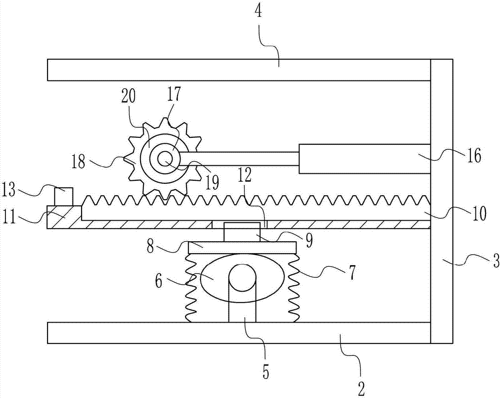
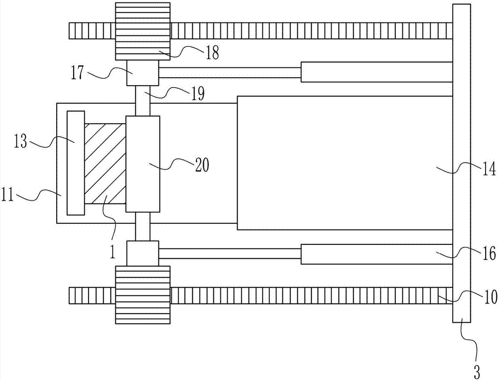
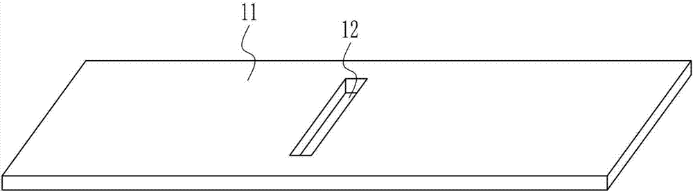
[0030] A paper placement and cutting device for an offset printing machine, such as Figure 1-7 As shown, it includes a base plate 2, a support plate 3, a top plate 4, a first pole 5, an electric cam 6, a spring 7, a push plate 8, a blade 9, a rack 10, a placement plate 11, a magnet 13, a horizontal plate 14, Cylinder 16, bearing block 17, gear 18, rotating shaft 19, reel 20 and second strut 21, the right side of bottom plate 2 is vertically connected with support plate 3 by the mode of welding connection, the left side top of support plate 3 The top plate 4 is horizontally connected by welding, the top of the bottom plate 2 is vertically connected with the first pole 5 by welding, and the front side top of the first pole 5 is connected with the electric cam 6 in a rotating manner. The base plate 2 tops on the left and right sides of the cam 6 are all vertically provided with a spring 7, and one end of the spring 7 is connected with the base plate 2 by welding, and the other e...
PUM
Abstract
The invention relates to a device for an offset press, particularly relates to a paper placing and cutting device for the offset press, and aims to realize the technical effects that the labor intensity of workers can be reduced, the cutting efficiency can be improved, the cutting cost can be reduced, and white paper can be stored in order. The paper placing and cutting device for the offset press comprises a bottom plate, a supporting plate, a top plate, a first supporting rod, an electric cam, springs, a push plate, a blade, a rack, a placing plate, a magnet, a cross plate, air cylinders, a bearing seat and the like, and the supporting plate is vertically connected with the right side face of the bottom plate in a welding mode. According to the device, the long white paper is wound around a winding drum and cut by using the blade, and therefore the labor intensity of the workers can be reduced, the cutting efficiency can be improved, and the cutting cost can be reduced.
Description
technical field [0001] The invention relates to a device for an offset printing machine, in particular to a paper placement and cutting device for an offset printing machine. Background technique [0002] The offset printing machine is a kind of lithographic printing machine. When printing, the printed image and text are first printed from the printing plate to the rubber cylinder, and then transferred to the paper by the rubber cylinder. Offset printing machines can be divided into sheet-fed offset printing machines and web offset printing machines according to different feeding methods; according to the number of printing colors completed in one pass, they can be divided into single-color, two-color, four-color and multi-color printing machines; The largest paper format can be divided into small offset printing machines, six-fold, four-fold, folio and full-sheet printing machines, and there is also a double-sided printing machine that can print on both sides at the same ti...
Claims
Application Information
Patent Timeline
Application Date:The date an application was filed.
Publication Date:The date a patent or application was officially published.
First Publication Date:The earliest publication date of a patent with the same application number.
Issue Date:Publication date of the patent grant document.
PCT Entry Date:The Entry date of PCT National Phase.
Estimated Expiry Date:The statutory expiry date of a patent right according to the Patent Law, and it is the longest term of protection that the patent right can achieve without the termination of the patent right due to other reasons(Term extension factor has been taken into account ).
Invalid Date:Actual expiry date is based on effective date or publication date of legal transaction data of invalid patent.