Steel plate clad cutting device for circuit board production

A technology for cutting equipment and circuit boards, which is applied in the directions of printed circuits, printed circuit manufacturing, and manufacturing of printed circuit precursors, which can solve the problems of bulky machines, low cutting precision, and poor cutting effects.

Active Publication Date: 2017-07-28
秦皇岛市东旭达黏胶制品有限公司
View PDF6 Cites 32 Cited by
  • Summary
  • Abstract
  • Description
  • Claims
  • Application Information

AI Technical Summary

Problems solved by technology

[0006] In order to overcome the shortcomings of the current machine for cutting circuit boards, which are too bulky, have low cutting precision, and poor cutting effect, the technical problem to be solved by the present invention is to provide a light weight, high cutting precision, and good cutting effect for circuit board production. Clad Steel Cutting Equipment

Method used


Image

  • Steel plate clad cutting device for circuit board production
  • Steel plate clad cutting device for circuit board production
  • Steel plate clad cutting device for circuit board production

Examples


Embodiment 1

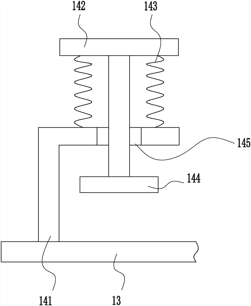
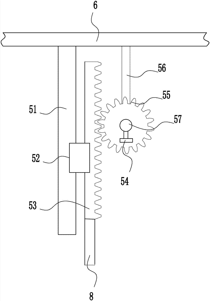
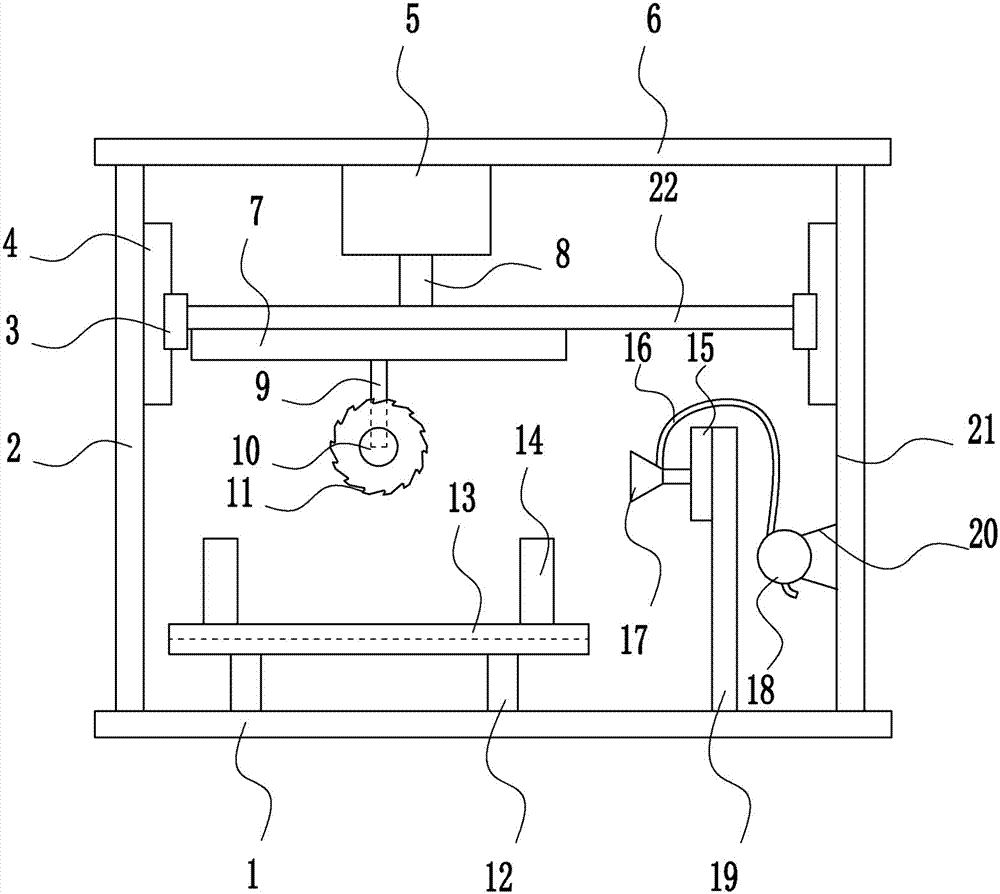
[0037] A kind of clad steel plate cutting equipment for circuit board production, such as Figure 1-6 As shown, it includes a bottom plate 1, a left frame 2, a first slider 3, a first slide rail 4, a lifting device 5, a top plate 6, a moving device 7, a lifting rod 8, a mounting rod 9, a second motor 10, and a blade 11 , the first bracket 12, the placement table 13, the fixing device 14, the swinging device 15, the hose 16, the nozzle 17, the air pump 18, the first mounting plate 19, the mounting seat 20, the right frame 21 and the moving plate 22, the top left of the bottom plate 1 The left frame 2 is welded on the side, the right frame 21 is welded on the top right side of the bottom plate 1, the top plate 6 is welded on the top of the left frame 2 and the right frame 21, a lifting device 5 is arranged in the middle of the bottom of the top plate 6, and a lifting rod is connected to the bottom of the lifting device 5 8. A moving plate 22 is welded to the bottom end of the el...

Embodiment 2

[0039] A kind of clad steel plate cutting equipment for circuit board production, such as Figure 1-6 As shown, it includes a bottom plate 1, a left frame 2, a first slider 3, a first slide rail 4, a lifting device 5, a top plate 6, a moving device 7, a lifting rod 8, a mounting rod 9, a second motor 10, and a blade 11 , the first bracket 12, the placement table 13, the fixing device 14, the swinging device 15, the hose 16, the nozzle 17, the air pump 18, the first mounting plate 19, the mounting seat 20, the right frame 21 and the moving plate 22, the top left of the bottom plate 1 The left frame 2 is welded on the side, the right frame 21 is welded on the top right side of the bottom plate 1, the top plate 6 is welded on the top of the left frame 2 and the right frame 21, a lifting device 5 is arranged in the middle of the bottom of the top plate 6, and a lifting rod is connected to the bottom of the lifting device 5 8. A moving plate 22 is welded to the bottom end of the el...

Embodiment 3

[0042] A kind of clad steel plate cutting equipment for circuit board production, such as Figure 1-6 As shown, it includes a bottom plate 1, a left frame 2, a first slider 3, a first slide rail 4, a lifting device 5, a top plate 6, a moving device 7, a lifting rod 8, a mounting rod 9, a second motor 10, and a blade 11 , the first bracket 12, the placement table 13, the fixing device 14, the swinging device 15, the hose 16, the nozzle 17, the air pump 18, the first mounting plate 19, the mounting seat 20, the right frame 21 and the moving plate 22, the top left of the bottom plate 1 The left frame 2 is welded on the side, the right frame 21 is welded on the top right side of the bottom plate 1, the top plate 6 is welded on the top of the left frame 2 and the right frame 21, a lifting device 5 is arranged in the middle of the bottom of the top plate 6, and a lifting rod is connected to the bottom of the lifting device 5 8. A moving plate 22 is welded to the bottom end of the el...


PUM


Abstract

The invention relates to a steel plate clad cutting device, in particular to a steel plate clad cutting device for circuit board production. The steel plate clad cutting device for the circuit board production aims to achieve the technical effects of being light, handy, high in cutting precision and good in cutting effect. The steel plate clad cutting device for the circuit board production comprises a base plate, a left frame, a first sliding block, a first sliding rail, a lifting device, a top plate, a moving device, a lifting rod, an installation rod, a second motor, a blade, a first support and the like. The left frame is welded to the left side of the top of the base plate. A right frame is welded to the right side of the top of the base plate. The top plate is welded to the top ends of the left frame and the right frame. The lifting device is arranged in the middle of the bottom of the top plate. According to the steel plate clad cutting device for the circuit board production, a worker manually shakes a rocker bar, the lifting device is controlled to move up and down, the height of the blade is controlled to be more appropriate, the cutting effect is better, and the blade is driven to move leftwards and rightwards through the moving device.

Description

technical field [0001] The invention relates to a steel-clad cutting equipment, in particular to a steel-clad cutting equipment for circuit board production. Background technique [0002] Cutting is a physical action. Cutting in a narrow sense refers to cutting objects (such as food, wood and other objects with low hardness) with sharp tools such as knives; cutting in a broad sense refers to using tools, such as machine tools, flames, etc. down to disconnect. There is also a "cutting line" extended in mathematics, which refers to a straight line that can divide a plane into several parts. Cutting plays an important role in people's production and life. [0003] The names of the circuit boards are: ceramic circuit board, alumina ceramic circuit board, aluminum nitride ceramic circuit board, circuit board, PCB board, aluminum substrate, high frequency board, thick copper board, impedance board, PCB, ultra-thin circuit board, ultra-thin Thin circuit boards, printed circuit ...

Claims


Application Information

Patent Timeline
Patent Type & Authority Applications(China)
IPC IPC(8): B26D1/18B26D7/02B26D7/18B26D7/26H05K3/02
CPCB26D1/185B26D7/025B26D7/1854B26D7/2635B26F2210/08H05K3/022
Inventor 不公告发明人
Owner 秦皇岛市东旭达黏胶制品有限公司
Why Eureka
Try Eureka