Auto-control new energy vehicle charging device

A new energy vehicle and charging device technology, applied in electric vehicle charging technology, charging stations, coupling devices, etc., can solve the problems of easy arcing, casualties, time-consuming and laborious, etc., to improve work efficiency, reduce equipment investment, reduce The effect of manufacturing cost

Inactive Publication Date: 2017-07-28
XIAMEN YINLV JIEYUAN ENVIRONMENTAL PROTECTION TECH CO LTD
View PDF5 Cites 42 Cited by
  • Summary
  • Abstract
  • Description
  • Claims
  • Application Information

AI Technical Summary

Problems solved by technology

Electric vehicles are inseparable from charging piles, but in the process of charging electric vehicles with existing charging piles, they are all manually plugged and unplugged by personnel. During the plugging and unplugging process, the charging plug is prone to arc due to the influence of voltage, and the generation of arc is easy to cause The electric shock of the user has a certain potential danger to the user, which will cause safety accidents and cause casualties. Moreover, the force of the personnel is unstable w...

Method used


Image

  • Auto-control new energy vehicle charging device
  • Auto-control new energy vehicle charging device
  • Auto-control new energy vehicle charging device

Examples


Embodiment Construction

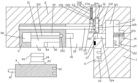
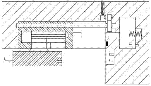
[0027] Such as Figure 1-Figure 8 As shown, a self-controlled new energy vehicle charging device of the present invention includes a pile body 1, a beam 2 fixedly arranged on the upper left side of the pile body 1, and a charging gun head 4, and the pile body below the beam 2 1 is provided with a plug-in slot 11, and the plug-in slot 11 is provided with a conductive pin 111, and the bottom end surface of the right side of the beam 2 is provided with a first sliding slot 21, and the first sliding slot 21 is provided with a Clamping and locking mechanism 3, the first sliding groove 21 is provided with the first screw rod 211 that is threadedly connected with the clamping and locking mechanism 3 and extends to the left and right sides, the pile body on the right side of the beam 2 1 is provided with a first sliding chamber 12, a through groove 13 is provided between the first sliding chamber 12 and the first sliding groove 21, and a first Cavity 16, a second cavity 22 is provide...


PUM


Abstract

The invention discloses an auto-control new energy vehicle charging device. The auto-control new energy vehicle charging device comprises a pile body, a beam fixedly arranged on the upper portion of the left side of the pile body and a charging gun point. A plug-in groove is formed in the position, below the beam, of the pile body and internally provided with a conductive contact pin. A first sliding groove is formed in the end face of the bottom of the right side of the beam and internally provided with a clamping locking mechanism and a first threaded rod which is connected with the clamping locking mechanism in a screw-threaded fit mode and extends towards the left side and the right side, a first sliding cavity is formed in the position, on the right side of the beam, of the pile body, and a through groove is formed between the first sliding cavity and the first sliding groove. A first cavity is formed in the position, above the through groove, of the pipe body, a second cavity is formed in the position, above the right side of the first sliding groove, of the beam, and a second sliding groove used for penetrating through the top wall of the beam is formed in the position, above the second cavity, of the beam. A push rod arranged opposite to the left side end of the through groove is arranged on the end face of the right side of the clamping locking mechanism, and a sliding block is connected into the first sliding cavity in a sliding-fit mode. The auto-control new energy vehicle charging device is simple in structure and convenient to plug, plug-in is automatically locked, and meanwhile the intelligent prompting function is achieved.

Description

technical field [0001] The invention relates to the technical field of new energy vehicle charging, in particular to a self-controlled new energy vehicle charging device. Background technique [0002] An electric vehicle refers to a vehicle powered by an on-board power supply and driven by a motor to drive the wheels. Compared with gasoline vehicles, it is more energy-saving and environmentally friendly, so it is being promoted by countries all over the world. Electric vehicles are inseparable from charging piles, but in the process of charging electric vehicles with existing charging piles, they are all manually plugged and unplugged by personnel. During the plugging and unplugging process, the charging plug is prone to arc due to the influence of voltage, and the generation of arc is easy to cause The electric shock of the user has a certain potential danger to the user, which will cause safety accidents and cause casualties, and the force of the personnel is unstable whe...

Claims


Application Information

Patent Timeline
IPC IPC(8): B60L11/18H01R13/629
CPCB60L53/16H01R13/629H01R2201/26Y02T10/70Y02T10/7072Y02T90/14
Inventor 鲁洁锋
Owner XIAMEN YINLV JIEYUAN ENVIRONMENTAL PROTECTION TECH CO LTD
Why Eureka
Try Eureka