Heavy type composite type buffer device used for belt conveyor

A belt conveyor and buffer device technology, applied in the direction of conveyors, conveyor objects, transportation and packaging, etc., can solve the problems of poor sealing, non-rotation of the blanking port, and the inability of the buffer bed to meet the conveying volume.

Inactive Publication Date: 2017-07-28
YICHANG LIANSHENG HI-TECH MASCH MFG CO LTD
View PDF0 Cites 1 Cited by
  • Summary
  • Abstract
  • Description
  • Claims
  • Application Information

AI Technical Summary

Problems solved by technology

[0003] The traditional loading part mainly uses buffer rollers before the buffer bed is used. It has been used for decades, but its design and working principle are likely to cause longitudinal and penetrating tearing of the conveyor belt, and because the buffer roller and the belt The impact contact method causes the sealing of the blanking port to be not tight, causing the material to fall and accumulate, and it is easy to cause problems such as belt deviation. The use of buffer rollers not only brings a lot of maintenance costs and waste of production capacity of the belt.
[0005] 1. The supporting roller has poor cushioning capacity and cannot absorb the strong impact force of falling materials well, and it is easy to smash the supporting roller, causing the hidden danger of longitudinal tearing of the belt
[0006] 2. The supporting frame of the support roller is easily deformed by the impact of the material frequently, the roller is easy to fall off, and the upright support seat of the support roller is easy to hang or tear the belt
[0007] 3. The support roller and the conveyor belt are in line contact, and the space between the two rollers is suspended, so it is easy for the material or other sh

Method used


Image

  • Heavy type composite type buffer device used for belt conveyor

Examples


Embodiment Construction

[0036] Embodiments of the present invention will be further described below in conjunction with the accompanying drawings.

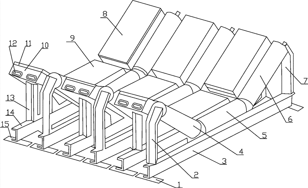
[0037] see figure 1 , a heavy-duty composite buffer device for a belt conveyor, which includes a buffer roller device and a buffer bed device, and the buffer roller device and the buffer bed device are arranged at intervals.

[0038] Further, the buffer idler device includes a support base 1, and a buffer idler support beam 3 is fixed between the support bases 1, and a left idler column 2 and a right idler column are respectively fixed at both ends of the buffer idler support beam 3. Roller column 7, the left buffer roller 4 is installed obliquely between the left roller column 2 and the buffer roller support beam 3, and the right buffer roller 6 is installed obliquely between the right idler column 7 and the buffer roller support beam 3 A middle buffer idler 5 is horizontally installed in the middle part of the buffer idler supporting crossbeam 3 .

...


PUM


Abstract

The invention relates to a heavy-duty compound buffer device for a belt conveyor, which comprises a buffer roller device and a buffer bed device, and the buffer roller device and the buffer bed device are arranged at intervals. The buffer idler device includes a support base, and a buffer idler support beam is fixed between the support bases, and a left idler column and a right idler column are respectively fixed at both ends of the buffer idler support beam, and the left idler column The left buffer roller is installed obliquely between the buffer roller support beam, the right buffer roller is installed obliquely between the right idler roller column and the buffer roller support beam, and the middle part of the buffer roller support beam is installed horizontally. Roller. This composite buffer combines the advantages of the buffer roller and the buffer bed, has double buffering effects, effectively overcomes the traditional single-structure buffer device, and improves the buffering effect.

Description

technical field [0001] The invention relates to the field of buffer devices, in particular to a heavy-duty composite buffer device for belt conveyors. Background technique [0002] Belt conveyors are widely used in food, medical, wharf, mining and other fields in my country; belt conveyors have strong conveying capacity, long conveying distance, simple structure and easy maintenance, and can easily implement programmed control and automatic operation. The belt conveyor is composed of conveyor belt, idler roller, rolling and driving, tensioning, redirection, loading, unloading, cleaning and other parts. [0003] The traditional loading part mainly uses buffer rollers before the buffer bed is used. It has been used for decades, but its design and working principle are likely to cause longitudinal and penetrating tearing of the conveyor belt, and because the buffer roller and the belt The impact contact method causes the material discharge port to be not tightly sealed, causin...

Claims


Application Information

Patent Timeline
IPC IPC(8): B65G15/60B65G39/06
CPCB65G15/60B65G39/06
Inventor 谢臣
Owner YICHANG LIANSHENG HI-TECH MASCH MFG CO LTD
Why Eureka
Try Eureka