Bridge construction equipment

A bridge construction and equipment technology, applied in bridge construction, bridge erection/assembly bridge, etc., can solve the problems of low degree of automation, achieve the effect of increasing stirring efficiency and reducing the probability of cement slurry damage

Active Publication Date: 2017-07-28
新昌县建凯电机有限公司
View PDF5 Cites 4 Cited by
  • Summary
  • Abstract
  • Description
  • Claims
  • Application Information

AI Technical Summary

Problems solved by technology

[0002] With the development of society, the construction of bridges is developing rapidly nowadays. It has developed from simple single-plank bridges and river-crossing bridges to sea-crossing bridges. During the construction of bridges, cement slurry is indispensable. The agitation of cement slurry requires Continuous, so as to prevent the cement slurry from being solidified and unusable. The existing cement slurry mixer needs to manually switch the switch door during the stirring process, and the degree of automation is not high. Therefore, the existing mixer has certain defects.

Method used


Image

  • Bridge construction equipment
  • Bridge construction equipment
  • Bridge construction equipment

Examples


Embodiment Construction

[0021] All features disclosed in this specification, or steps in all methods or processes disclosed, may be combined in any manner, except for mutually exclusive features and / or steps.

[0022] Any feature disclosed in this specification (including any appended claims, abstract and drawings), unless expressly stated otherwise, may be replaced by alternative features which are equivalent or serve a similar purpose. That is, unless expressly stated otherwise, each feature is one example only of a series of equivalent or similar features.

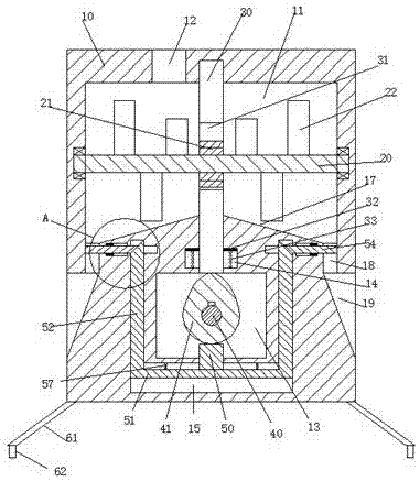
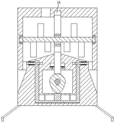
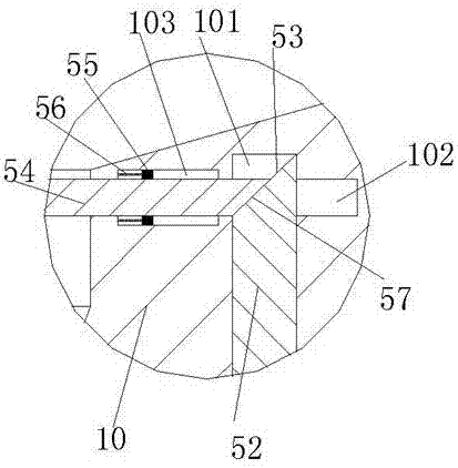
[0023] Such as Figure 1-4 As shown, a bridge construction equipment of the present invention includes a cement slurry frame 10, a support column 61 is provided on the bottom surface of the cement slurry frame 10, a universal wheel 62 is provided on the lower side of the support column 61, and the support The column 61 is arranged obliquely so as to increase the stability. The grout housing 10 is provided with a grout chamber 11, and a swivel...


PUM


Abstract

Bridge construction equipment comprises a cement paste frame body. Supporting columns are arranged on the bottom face of the cement paste frame body. Universal wheels are arranged on the lower sides of the supporting columns. A cement paste containing cavity is formed in the cement paste frame body. A rotating rod is installed between the left end and the right end of the cement paste containing cavity. A rotating toothed wheel is fixedly installed in the middle of the rotating rod. Stirring blades are further fixedly installed on the rotating rod. A setting cavity is formed in the bottom of the cement paste frame body. An oblique wheel is installed in the setting cavity through a first rotating rod. A main slipping cavity is further formed in the bottom, located at the lower end of the setting cavity, of the cement paste frame body. Side slipping cavities extending up and down are formed in the left and right sides of the main slipping cavity correspondingly. A slipping plate is installed in the main slipping cavity in a slipping mode. A slipping arm is installed in each side slipping cavity in a slipping mode. The slipping arms are fixedly connected with the slipping plate. A pushing bevel face is further arranged at the upper end of each slipping arm. A thrust arm is fixedly installed in the middle of the upper end of the slipping plate, extends upward and penetrates into the setting cavity.

Description

technical field [0001] The invention relates to the field of bridge equipment, in particular to bridge construction equipment. Background technique [0002] With the development of society, the construction of bridges is developing rapidly nowadays. It has developed from simple single-plank bridges and river-crossing bridges to sea-crossing bridges. During the construction of bridges, cement slurry is indispensable. The agitation of cement slurry requires Continuous, so as to prevent the cement slurry from being solidified and unusable. The existing cement slurry mixer needs to manually open and close the switch door during the stirring process, and the degree of automation is not high. Therefore, the existing mixer has certain defects. Contents of the invention [0003] The object of the present invention is to provide a bridge construction equipment and its use method, which can overcome the above-mentioned defects of the prior art. [0004] According to the present inv...

Claims


Application Information

Patent Timeline
Patent Type & Authority Applications(China)
IPC IPC(8): E01D21/00
CPCE01D21/00
Inventor 刘建华
Owner 新昌县建凯电机有限公司
Why Eureka
Try Eureka