Integrated ceiling system

A technology that integrates suspended ceilings and ceiling panels, applied in the direction of ceilings, building components, buildings, etc., can solve the problems of low installation efficiency and cumbersome construction steps, and achieve the effect of shortening installation time and convenient disassembly and assembly process.

Active Publication Date: 2017-07-28
HUNAN INST OF TECH
View PDF5 Cites 8 Cited by
  • Summary
  • Abstract
  • Description
  • Claims
  • Application Information

AI Technical Summary

Problems solved by technology

The existing ceiling installation technology is to fix multiple main keels under the ceiling through hooks, and then fix the auxiliary keels on the main keels. In this process, a large number of expansion screws need to be driven in to ensure the connection between the keels. Stability (for example, when the main keel of the suspended ceiling adopts 20×40 wooden keel, it needs to be fixed with the original structure floor with φ8×80 expansion screws; Tapping screws should be fixed reasonably, and the auxiliary keel against the wall should be fixed with an expansion screw about every 800mm), and finally the gypsum board (that is, the ceiling board) is fixed on the keel with special screws. The entire construction process is very cumbersome and the installation efficiency Low

Method used


Image

  • Integrated ceiling system
  • Integrated ceiling system
  • Integrated ceiling system

Examples


Embodiment Construction

[0033] In order to facilitate the understanding of those skilled in the art, the present invention will be further described below in conjunction with the embodiments and accompanying drawings, and the contents mentioned in the embodiments are not intended to limit the present invention.

[0034] In describing the present invention, it is to be understood that the terms "upper", "lower", "front", "rear", "left", "right", "vertical", "horizontal", "top", The orientation or positional relationship indicated by "bottom", "inner", "outer", etc. is based on the orientation or positional relationship shown in the drawings, and is only for the convenience of describing the present invention and simplifying the description, rather than indicating or implying the referred device Or elements must have a certain orientation, be constructed and operate in a certain orientation, and thus should not be construed as limiting the invention.

[0035] In the description of the present invention...


PUM


Abstract

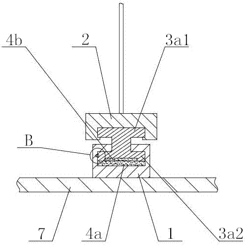
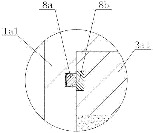
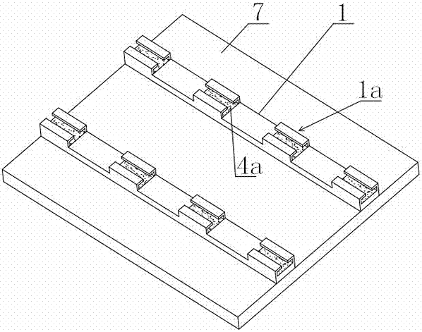
An integrated ceiling system relates to the technical field of ceiling decoration. The integrated ceiling system comprises a plurality of ceiling panels, hang suction seats mounted on the back faces of the ceiling panels, a keel for mounting below a ceiling, and connecting members for connecting the hang suction seats and the keel; the hang suction seats are of strip-shaped structure and provided with a plurality of locking parts at intervals, each locking part comprises two limiting hook planes symmetrically arranged on the upper surfaces of the hang suction seats, and first magnets are arranged in the locking parts; a sliding groove is formed in the keel; the connecting members comprises a plurality of sliding blocks arranged at intervals and connecting rods for connecting the sliding blocks, the spacing of the adjacent sliding blocks on the connecting members is same as the spacing of the adjacent locking parts on the hook suction seats, and the sliding blocks are provided with upper clamping tongues and lower clamping tongues; and the upper clamping tongues are arranged in the sliding groove, baffles are mounted on the two ends of the sliding groove, the lower clamping tongues are embedded in a second magnet, and the limiting hook planes can hang the lower clamping tongues in a sleeving mode. The integrated ceiling system does not need to hit into a large number of screws on the keel when the ceiling is mounted, the installation time can be shortened, and meanwhile, disassembling is quite convenient.

Description

technical field [0001] The invention relates to the technical field of suspended ceiling decoration, in particular to an integrated suspended ceiling system. Background technique [0002] In the process of interior decoration, people often install suspended ceiling structures. On the one hand, they can be used to cover beams, pipes, lines, etc. on the roof. On the other hand, they can also be used to design shapes and play an aesthetic role. The existing ceiling installation technology is to fix multiple main keels under the ceiling through hooks, and then fix the auxiliary keels on the main keels. In this process, a large number of expansion screws need to be driven in to ensure the connection between the keels. Stability (for example, when the main keel of the suspended ceiling is made of 20×40 wooden keel, it needs to be fixed with the original structure floor with φ8×80 expansion screws; when the auxiliary keel is made of 20×40 wooden keel, it needs to use self Tapping ...

Claims


Application Information

Patent Timeline
Patent Type & Authority Applications(China)
IPC IPC(8): E04B9/00E04B9/06E04B9/22
CPCE04B9/00E04B9/06E04B9/22
Inventor 廖师思肖峰邬锋欧阳彦红
Owner HUNAN INST OF TECH
Why Eureka
Try Eureka