Online degritting device at bottom of horizontal-type oil-gas-water three phase separator and degritting method

A three-phase separator, oil-water separation technology, applied in separation methods, chemical instruments and methods, liquid separation, etc., can solve problems such as the inability to ensure the effective removal of deposited solid impurities, the inability to enter the sand removal space, and the lack of consideration of jet nozzles. , to reduce the cost of human intervention, smooth the sand removal process, and reduce the risk of clogging the sand outlet.

Active Publication Date: 2017-07-28
中石化石油工程技术服务有限公司 +1
View PDF14 Cites 3 Cited by
  • Summary
  • Abstract
  • Description
  • Claims
  • Application Information

AI Technical Summary

Problems solved by technology

Although this method can achieve the purpose of collecting solid impurities inside the separator, it does not consider that the disturbance of the jet nozzle will affect the oil-water separation process in the settling chamber, which may cause the deposited solid impurities to roll and re-enter the oil-water settling space, resulting in poor separation
Patent CN 204663511 U considers this problem, and an orifice layer is set above the jet nozzle, which avoids the mixing of the jet tumbling water and the oil-water in the settlement space, but this will also cause a large amount of solid impurities to be deposited on the orifice layer, However, the sand removal space below the orifice layer cannot be accessed, and the effective removal of deposited solid impurities cannot be guaranteed.
The above two devices also have a common shortcoming, that is, the solid impurities collected by the nozzle jet first gather at the sand discharge port, and the solid impurities have a high density and accumulate in the sand discharge port. The longer the time, the denser they become. When there is sand, it is very likely that the flow will not be smooth, causing blockage, resulting in sand discharge failure

Method used


Image

  • Online degritting device at bottom of horizontal-type oil-gas-water three phase separator and degritting method
  • Online degritting device at bottom of horizontal-type oil-gas-water three phase separator and degritting method
  • Online degritting device at bottom of horizontal-type oil-gas-water three phase separator and degritting method

Examples


Embodiment Construction

[0046] The present invention will be further described below in conjunction with the accompanying drawings and specific embodiments, so that those skilled in the art can better understand the present invention and implement it, but the examples given are not intended to limit the present invention.

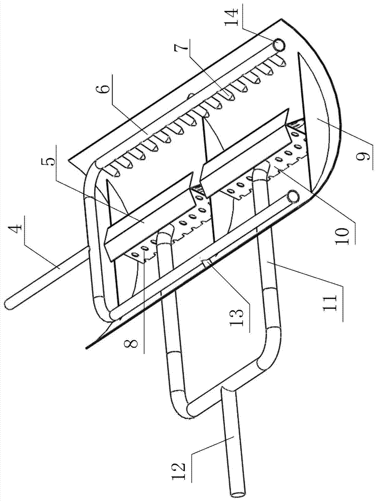
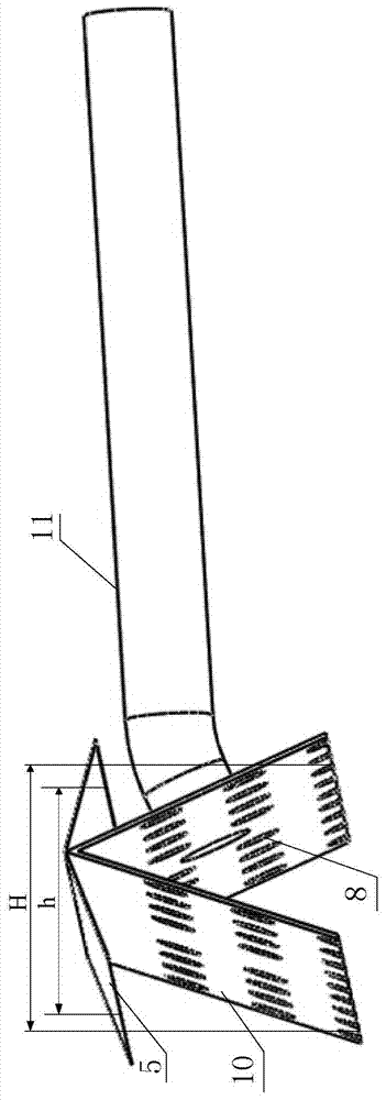
[0047] Such as figure 1 As shown, the online desanding device 1 at the bottom of a horizontal oil-gas-water three-phase separator of the present invention includes a sand separating plate 9, a sand gathering plate 10, a disturbance hole 8, a flow stabilization plate 5, a sand suction pipe 11, a suction Sand manifold 12, water inlet main pipe 4, water inlet branch pipe 6, jet nozzle 7, etc.

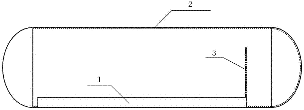
[0048] combine image 3 As shown, the horizontal oil-gas-water three-phase separator 2 is provided with an oil pool partition 3, which divides the inside of the horizontal oil-gas-water three-phase separator into an oil-water separation area (corresponding to the water inlet side) and an oil ac...


PUM

PropertyMeasurementUnit
pore sizeaaaaaaaaaa

Abstract

The invention discloses an online degritting device at the bottom of a horizontal-type oil-gas-water three phase separator and a degritting method. An oil-bath clapboard is arranged in the horizontal-type oil-gas-water three phase separator and divides the horizontal-type oil-gas-water three phase separator into an oil-water separation area and an oil collecting area. The online degritting device is arranged at the bottom of the horizontal-type oil-gas-water three phase separator and correspondingly located in the oil-water separation area. The online degritting device comprises a water inlet pipe, a plurality of grit-separating plates, at least one grit-collecting plate, at least one flow-stabilizing plate and a grit-absorbing pipe. According to the device, the functional modules are tightly matched, and the device occupies a small volume space of the three phase separator; and the device has small influence on the oil-gas-water normal separation process in the separator, online clearing of solid impurities in the separator and automatic control over the process can be achieved, manpower interference cost is reduced, and production efficiency is improved.

Description

technical field [0001] The invention belongs to the field of surface engineering of oil and gas fields, and in particular relates to an online desanding device and a desanding method at the bottom of an oil-gas-water three-phase separator. Background technique [0002] In oil and gas field surface engineering, oil well production fluid is mostly a mixed fluid composed of oil, gas, water, etc., and the mixed fluid migrates in the formation pores and wellbore, inevitably carrying solid impurities such as mud and sand. The horizontal oil, gas and water three-phase separator is an indispensable equipment for the preliminary separation of production fluids. The existence of solid impurities will wear the sealing surface of the valve, cause blockage of the internal components of the separator, and deposit at the bottom of the separator, reducing the The effective volume of oil-water separation is small, which reduces the separation efficiency, hinders the normal operation of the s...

Claims


Application Information

Patent Timeline
Patent Type & Authority Applications(China)
IPC IPC(8): E21B43/34B01D17/028B01D21/02B01D21/26
CPCB01D17/0211B01D21/02B01D21/267E21B43/34
Inventor 陈建磊刘建武纪国庆文彬范伟韩梦媛李毅马旭史林青徐辉
Owner 中石化石油工程技术服务有限公司
Why Eureka
Try Eureka