Check patentability & draft patents in minutes with Patsnap Eureka AI!

A biomass fuel boiler

A biomass fuel and boiler technology, which is applied in the field of combustion boilers, can solve the problems of reducing fuel burnout rate and heat loss, and achieve the effect of improving heat exchange efficiency and improving burnout rate.

Active Publication Date: 2019-06-21
吉林市安瑞克能源科技开发有限公司
View PDF10 Cites 0 Cited by
  • Summary
  • Abstract
  • Description
  • Claims
  • Application Information

AI Technical Summary

Problems solved by technology

[0002] Biomass fuel has been plagued by the development of biomass boilers due to the diversity of raw materials, different processing techniques, high fuel ash content, and coking in combustion. For traditional biomass fuel boilers, in order to ensure output power, its combustion The design of the surface and furnace is relatively large, but when burning biomass fuel with coking characteristics, because the combustion surface is too large and the material layer is too thick, it vibrates with the grate, and a large amount of unburned fuel is mixed with unburnable ash. , into the low end of the grate, forming a thick material layer, the bottom of the grate is the dead zone of the secondary air, the temperature is low, and the primary air cannot penetrate the material layer, so coke slag is generated, which reduces the fuel burnout rate and causes certain heat loss

Method used


Image

  • A biomass fuel boiler
  • A biomass fuel boiler
  • A biomass fuel boiler

Examples


Embodiment Construction

[0023] Embodiments of the present invention are described in detail below, examples of which are shown in the drawings, wherein the same or similar reference numerals designate the same or similar elements or elements having the same or similar functions throughout. The embodiments described below by referring to the figures are exemplary and are intended to explain the present invention and should not be construed as limiting the present invention.

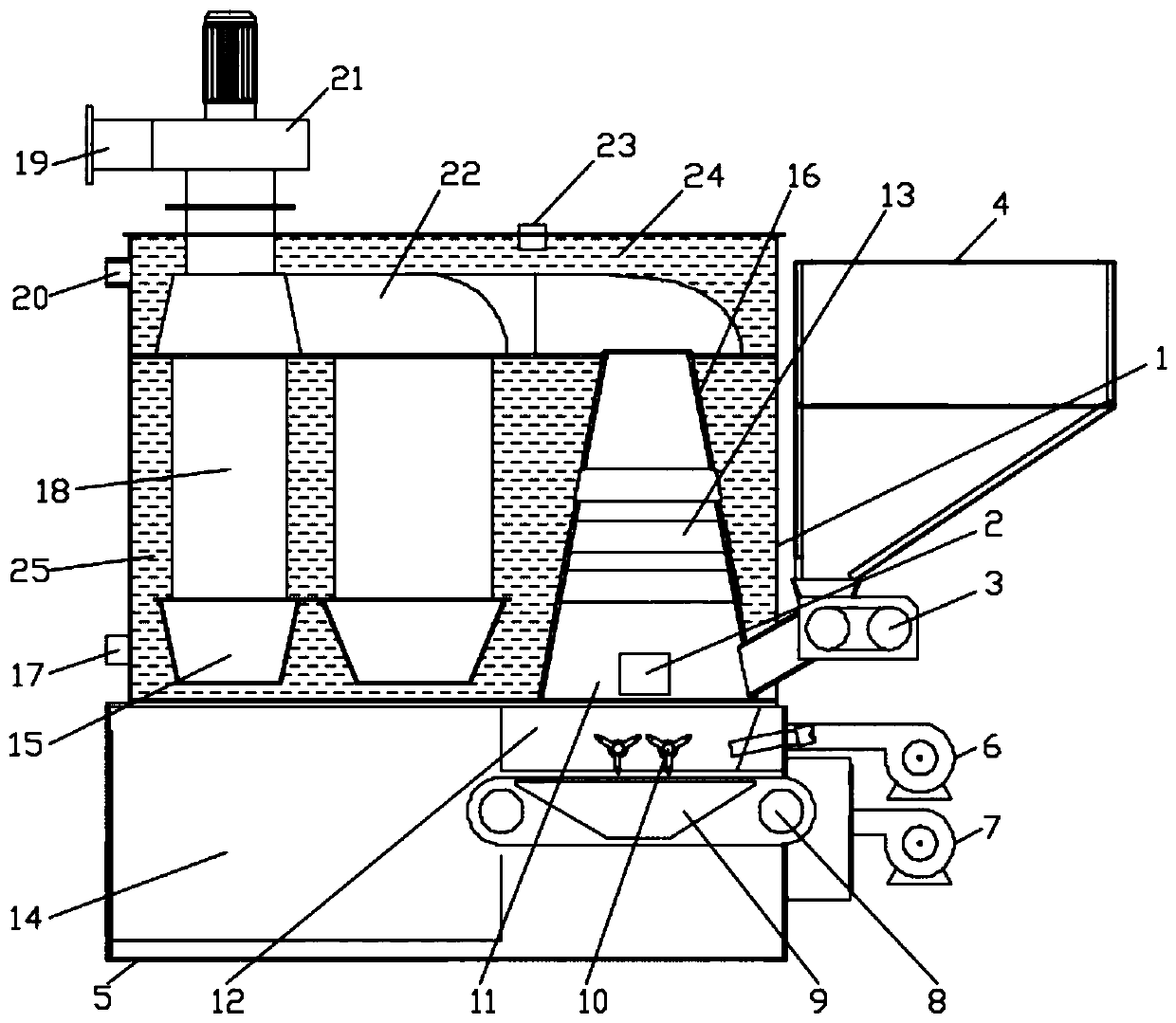
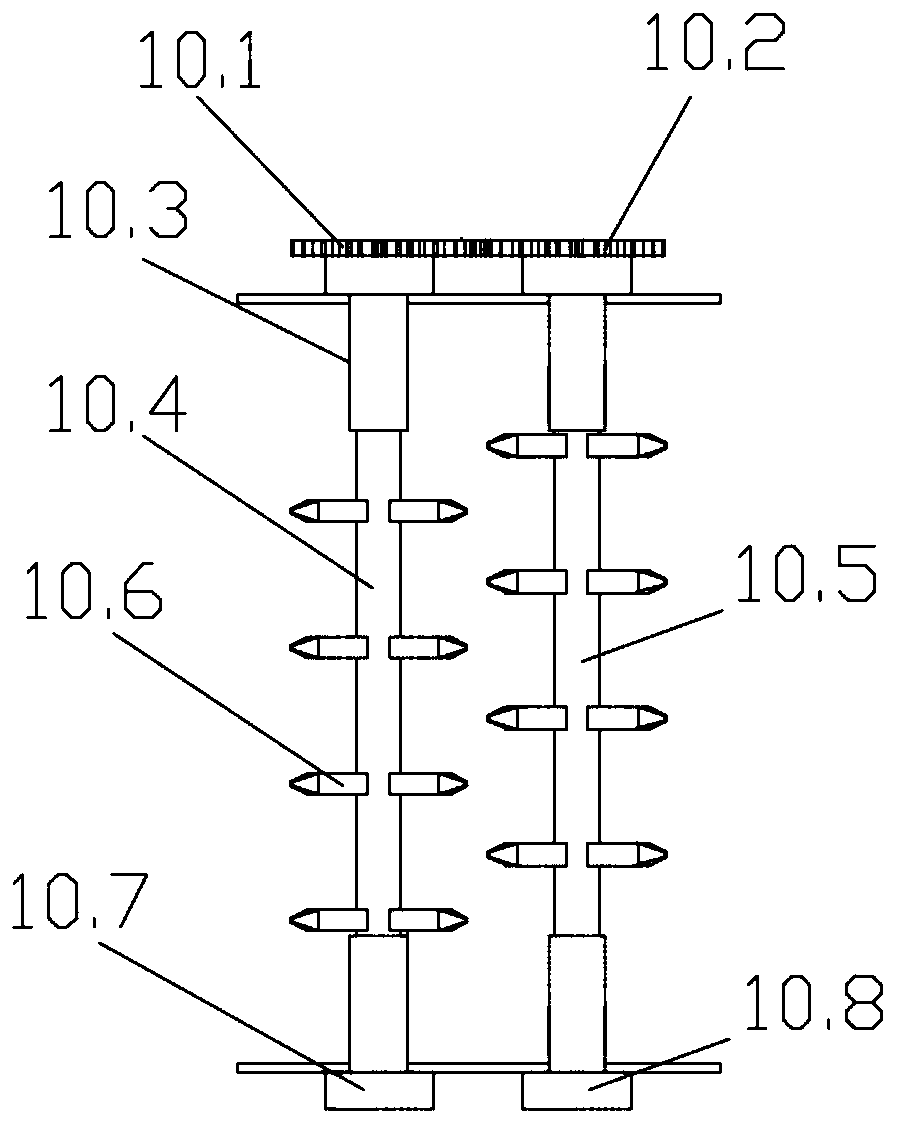
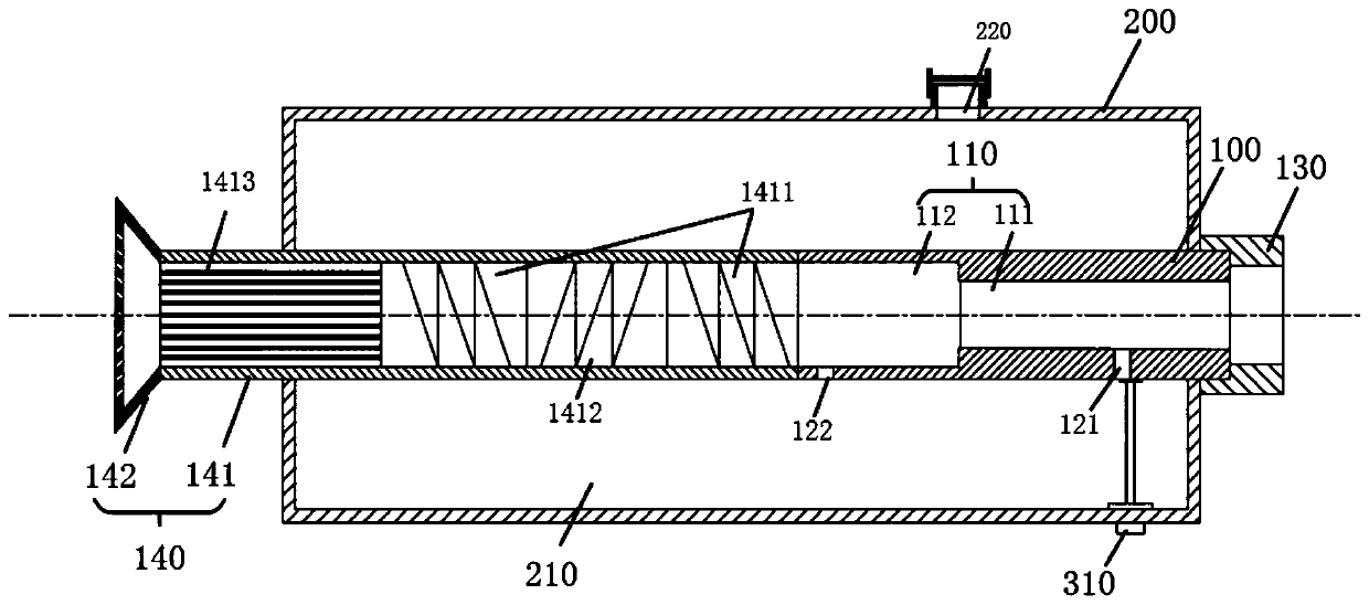
[0024] figure 1 is a schematic structural view of a biomass fuel boiler in an embodiment of the present invention; figure 2 It is a structural schematic diagram of a poking device according to an embodiment of the present invention; image 3 is a schematic structural view of the cleaning nozzle of the embodiment of the present invention; Figure 4 It is a structural schematic diagram of the atomizing part of the atomizing nozzle of the embodiment of the present invention; Figure 5 It is a structural schematic diagram of the ...


PUM


Abstract

The invention relates to a biomass fuel boiler. The biomass fuel boiler comprises a boiler body, a base, a heat accumulation type hearth, a combustion chamber, a first air distribution chamber and a controller. The boiler body comprises a first heat working medium centralizing chamber, a partition plate and a second heat working medium centralizing chamber. A water outlet pipe is arranged on the side wall of the first heat working medium centralizing chamber, a water inlet pipe is arranged at the top end of the first heat working medium centralizing chamber, and a flue is arranged in the first heat working medium centralizing chamber. A water return pipe is arranged on the side wall of the second heat working medium centralizing chamber. The base is arranged at the lower end of the boiler body. The heat accumulation type hearth is arranged in the boiler body, an air outlet of the heat accumulation type hearth communicates with an air inlet of the flue, and an induced draft fan is arranged at the position of an air outlet of the flue. The combustion chamber is arranged in the base and internally provided with a fire grate, a feeder penetrates an inlet of the combustion chamber and conducts feeding on the fire grate, and an outlet of the combustion chamber communicates with an air inlet of the heat accumulation type hearth. The first air distribution chamber is arranged in the base and internally provided with a first air blower, an air outlet of the first air blower communicates with the combustion chamber so as to blow air into the combustion chamber from the bottom of the combustion chamber, and the controller is electrically connected with the feeder, the induced draft fan and the first air blower. By means of the biomass fuel boiler, the burn-off rate of fuel can be effectively increased, and the heat exchange efficiency is improved.

Description

technical field [0001] The invention relates to the technical field of combustion boilers, in particular to a biomass fuel boiler. Background technique [0002] Biomass fuel has been plagued by the development of biomass boilers due to the diversity of raw materials, different processing techniques, high fuel ash content, and coking in combustion. For traditional biomass fuel boilers, in order to ensure output power, its combustion The design of the surface and furnace is relatively large, but when burning biomass fuel with coking characteristics, because the combustion surface is too large and the material layer is too thick, it vibrates with the grate, and a large amount of unburned fuel is mixed with unburnable ash. , into the low end of the grate, forming a thick material layer, the bottom of the grate is the dead zone of the secondary air, the temperature is low, and the primary air cannot penetrate the material layer, so coke slag is generated, which reduces the fuel b...

Claims


Application Information

Patent Timeline
Patent Type & Authority Patents(China)
IPC IPC(8): F24H1/34F24H9/18F23L9/06F23B10/02
CPCF23B10/02F23L9/06F24H1/34F24H9/1845
Inventor 单亚顺
Owner 吉林市安瑞克能源科技开发有限公司
Features
  • R&D
  • Intellectual Property
  • Life Sciences
  • Materials
  • Tech Scout
  • Unparalleled Data Quality
  • Higher Quality Content
  • 60% Fewer Hallucinations
Learn More