Projection data acquisition method of guide rail band for positioning
An acquisition method and projection data technology, applied in positioning, measuring devices, instruments, etc., can solve the problems of poor anti-interference and signal strength susceptible to interference, and achieve the effects of high sensitivity, convenient acquisition, and wide application range
- Summary
- Abstract
- Description
- Claims
- Application Information
AI Technical Summary
Problems solved by technology
Method used
Image
Examples
Embodiment 1
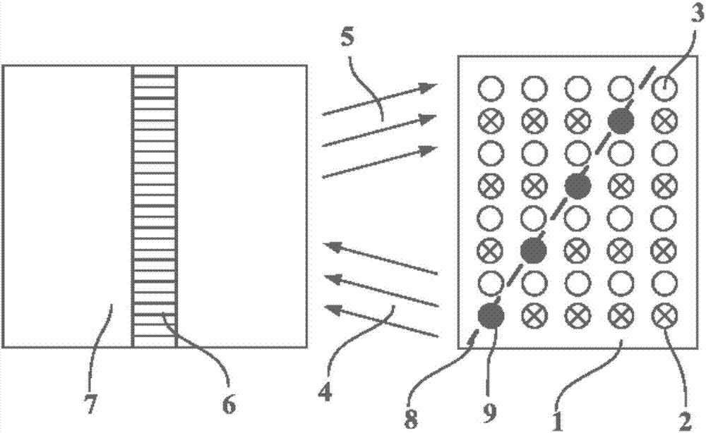
[0046] The method for obtaining projection based on distance detection or phase detection proposed in the embodiment of the present invention, combined with figure 1 , the method includes:
[0047] The transmitter 3 in the transmitter array transmits the positioning signal 4 to the guide rail belt 6 and the guide rail belt surrounding environment 7, and the positioning signal 5 reflected by the guide rail belt 6 and the guide rail belt surrounding environment 7 is received by the receiver array; The distances from the surrounding environment 7 to the transmitter-receiver array are different, and the receivers at different positions of the receiver array use the reflected positioning signal 5 to perform distance detection or phase detection. The results are different, and the detected distance or phase is within the set range of the receiver 9 forms a projection 8 on the background of receivers that detect other distances or phases.
[0048] figure 1 The transmitter 3 forms a...
Embodiment 2
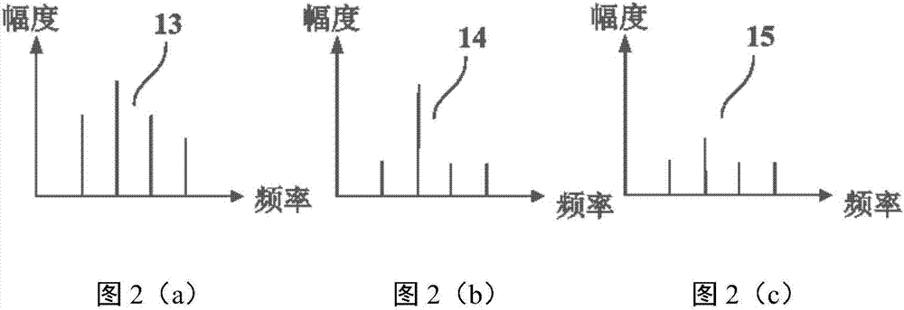
[0050] As a preferred embodiment of the present invention, the embodiment of the present invention proposes a method for obtaining projections based on frequency component detection of reflected signals, combined with figure 1 and Figure 2, the method includes:
[0051] The transmitter 3 transmits the positioning signal 4 to the guide rail belt 6 and the surrounding environment 7 of the guide rail belt, and the positioning signal 5 reflected by the guide rail belt 6 and the surrounding environment 7 of the guide rail belt is received by the receiver array; the positioning signal transmitted by the transmitter 3 includes at least two frequencies The frequency component of the fundamental wave is shown in Figure 2(a); the reflection characteristics of the guide track belt 6 and the guide track belt surrounding environment 7 to the positioning signal 4 are inconsistent; the detection result of the frequency component of the guide track belt 6 reflected signal is shown in Figure 2(...
Embodiment 3
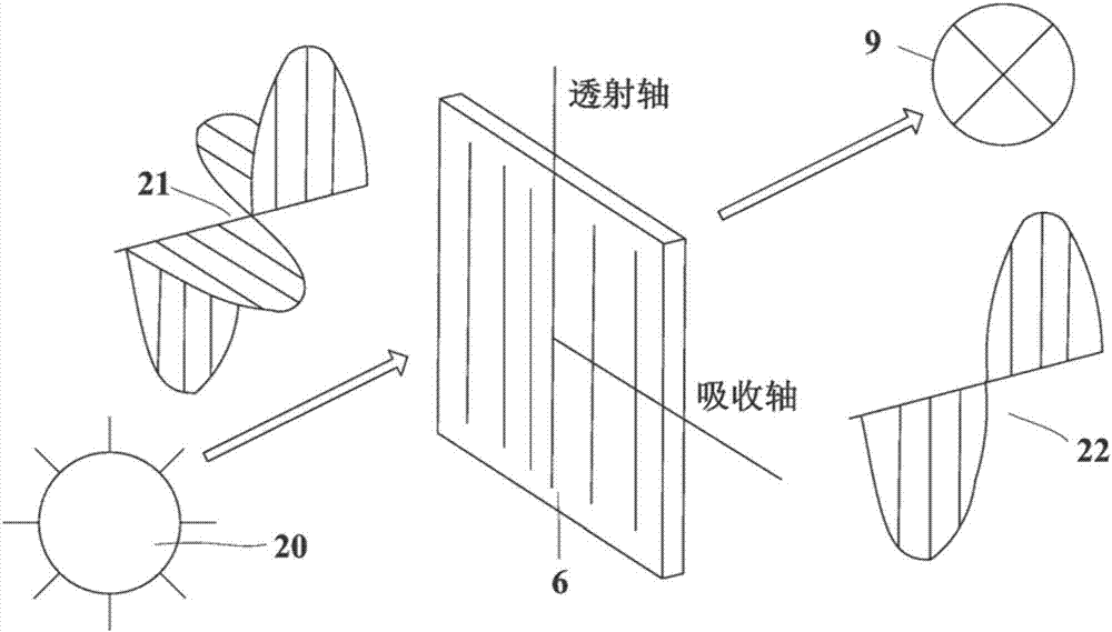
[0053] As a preferred embodiment of the present invention, the method for obtaining projection based on polarized light detection proposed in the embodiment of the present invention, combined with image 3 , the method includes:
[0054] The light emitted by the light source 20 has a polarization characteristic of 21, and the light polarization characteristic after being processed by the guide rail belt 6 (polarizer) is 22; The characteristic is 22; the analysis result of the receiver that has not received the light processed by the guide rail belt 6 is the polarization characteristic 21; the receiver with the analysis result of 22 forms a projection on the background formed by the receiver with the analysis result of 21.
PUM
 Abstract
Description
Claims
Application Information
 - R&D
- Intellectual Property
- Life Sciences
- Materials
- Tech Scout
- Unparalleled Data Quality
- Higher Quality Content
- 60% Fewer Hallucinations
Browse by: Latest US Patents, China's latest patents, Technical Efficacy Thesaurus, Application Domain, Technology Topic, Popular Technical Reports.
© 2025 PatSnap. All rights reserved.Legal|Privacy policy|Modern Slavery Act Transparency Statement|Sitemap|About US| Contact US: help@patsnap.com


