Visual experimental system for shake features of molten fuel tank during severe accidents of sodium-cooled fast reactor

A severe accident, sodium-cooled fast reactor technology, applied in the field of nuclear energy, can solve problems such as dense fuel distribution and recritical danger, and achieve the effects of simple operation, comprehensive research parameters, and strong scalability

Inactive Publication Date: 2017-07-28
SUN YAT SEN UNIV
View PDF6 Cites 3 Cited by
  • Summary
  • Abstract
  • Description
  • Claims
  • Application Information

AI Technical Summary

Problems solved by technology

Previous international studies have shown that when a core disintegration accident occurs in a sodium-cooled fast reactor, with the development of the accident, a molten fuel pool may be formed in the core area. Under the interaction between the fuel and the coolant liquid sodium, the molten fuel pool sloshing can occur causing the fuel distribution to become denser, creating the risk of recriticality

Method used


Image

  • Visual experimental system for shake features of molten fuel tank during severe accidents of sodium-cooled fast reactor
  • Visual experimental system for shake features of molten fuel tank during severe accidents of sodium-cooled fast reactor
  • Visual experimental system for shake features of molten fuel tank during severe accidents of sodium-cooled fast reactor

Examples


Embodiment 1

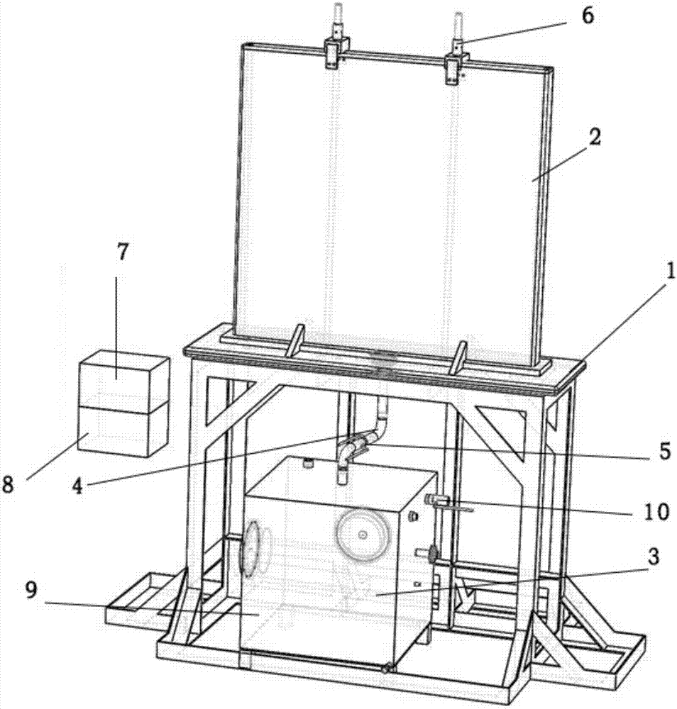
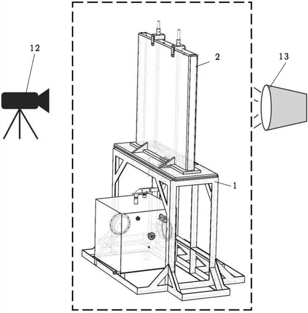
[0028] like figure 1 , 2 As shown in the figure, the visualized experimental system for the sloshing characteristics of the molten fuel pool during a severe accident of the sodium-cooled fast reactor provided by the present invention includes a support 1, a visualized experimental container 2 arranged on the support 1, a gas supply device 3, a gas conduit 4, and a jet valve. 5. Rod bundle structure 6, control module 7 and experimental environment monitoring module 8;

[0029] The bottom of the visual experiment container 2 is provided with a gas spout, and the gas spout of the visual experiment container 2 is connected to the gas supply device 3 through a gas conduit 4, and the gas jet valve 5 is installed on the gas conduit 4; the rod bundle structure 6 It is arranged on the top of the visual experimental container 2, and one end of it is inserted into the visual experimental container 2; the experimental environment monitoring module 8 is set in the visual experimental cont...

Embodiment 2

[0032] On the basis of Embodiment 1, the present invention further limits the specific structure of the visual experiment container 2 . like figure 1 , 2 shown:

[0033] The visual experiment container 2 provided in this embodiment can be one of a cuboid, a cube and a cylinder, and the top of the visual experiment container 2 of a cuboid, a cube and a cylinder is open. The specific shape of the visual experiment container 2 can be selected according to the needs of the experiment. For example, if two-dimensional experimental observation is to be performed, a thin-shaped visual experiment container 2 such as a rectangular parallelepiped-shaped visual experiment container 2 is selected, and its observation effect is better; For three-dimensional experimental observation, you can choose a cube or cylinder-shaped visual experiment container 2 . Among them, in order to facilitate the cleaning of the visual experiment container 2 after the experiment is completed, a discharge val...

Embodiment 3

[0037] In this embodiment, on the basis of Embodiment 1 and Embodiment 2, the gas supply device 3 is further described in detail. like figure 1 , 2As shown, the gas supply device 3 includes a main body 9, and a cavity for accommodating gas is opened in the main body 9. The top of the main body 9 is provided with an interface for connecting the gas conduit 4 and a pressure gauge, and the interface communicates with the cavity. The main body 9 is made of stainless steel, and its overall shape is a cube. One side of the main body 9 is provided with an intake valve 10 , which communicates with the cavity and is connected to the control module 7 . Under normal circumstances, there is gas stored in the main body 9, and its internal air pressure is relatively high, which meets the requirements of the experiment, but after many uses, the air pressure of the gas stored in the main body 9 is insufficient to support the next experiment. At this time, the main body 9 needs to be filled ...


PUM


Abstract

The invention relates to a visual experimental system for shake features of a molten fuel tank during severe accidents of a sodium-cooled fast reactor; the visual experimental system comprises a support, a visual experimental container arranged on the support, a gas supply device, a gas conduit, a gas spray valve, a rod structure, a control module and an experimental environment monitoring module, wherein the bottom of the visual experimental container is provided with a gas spout that is connected to the gas supply device through the gas conduit, the gas spray valve is mounted on the gas conduit, the rod structure is arranged at the top of the visual experimental container, and one end of the rod structure is extended into the visual experimental container to simulate a control rod structure of the sodium-cooled fast reactor; the experimental environment monitoring module is arranged in the visual experimental container; the experimental environment monitoring module, the gas spray valve and a control module are electrically connected.

Description

technical field [0001] The invention relates to the technical field of nuclear energy, and more particularly, to a visual experiment system for the sloshing characteristics of molten fuel pools during a severe accident of a sodium-cooled fast reactor. Background technique [0002] Compared with the previous three generations of nuclear power technology, the fourth generation of nuclear power technology has the advantages of better safety, higher economy, less nuclear waste and effective prevention of nuclear proliferation. As the preferred reactor type in the fourth generation of nuclear power technology in the world, sodium-cooled fast reactor represents the development trend and technological frontier of advanced nuclear energy systems. Therefore, it is of great significance to study the mechanism of severe core disintegration accidents in sodium-cooled fast reactors for slowing down and mitigating the consequences of accidents and ensuring the long-term healthy developmen...

Claims


Application Information

Patent Timeline
Patent Type & Authority Applications(China)
IPC IPC(8): G21C17/00
CPCG21C17/001Y02E30/30
Inventor 成松柏李硕李可嘉张楠林少鹏
Owner SUN YAT SEN UNIV
Why Eureka
Try Eureka