Plane cutting machine of motor rotor

A technology of plane cutting and motor rotor, which is applied in the manufacture of stator/rotor body, milling machine equipment details, metal processing, etc., can solve the problems of low production efficiency and achieve the effect of improving production efficiency

Inactive Publication Date: 2017-07-28
柳州众赢机械有限公司
View PDF3 Cites 0 Cited by
  • Summary
  • Abstract
  • Description
  • Claims
  • Application Information

AI Technical Summary

Problems solved by technology

[0002] The motor rotor plane cutting device is used to cut (remove) the motor rotor. The motor rotor plane cutting device in the prior art generally adopts a manual loading structure, and the production efficiency is low.

Method used


Image

  • Plane cutting machine of motor rotor

Examples


Embodiment Construction

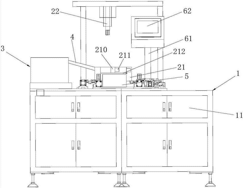
[0012] In order to make the object, technical solution and advantages of the present invention clearer, the present invention will be further described in detail below in conjunction with the accompanying drawings and embodiments. It should be understood that the specific embodiments described here are only used to explain the present invention, not to limit the present invention.

[0013] Such as figure 1 As shown, a motor rotor plane cutting machine provided by the embodiment of the present invention includes an equipment frame 1, a power box 11 is arranged under the equipment frame 1, and circuit boards and the like can be arranged in the power box 11. The equipment frame 1 A plane cutting device is arranged on it, and the plane cutting device includes a positioning mold 21 fixedly connected to the equipment frame 1 and a cutting tool 22 located above the positioning mold 21. The cutting tool 22 can be driven by a screw to slide up and down, and the cutting tool 22 may inc...


PUM


Abstract

The invention belongs to the technical field of motor rotor production devices, and provides a plane cutting machine of a motor rotor. The plane cutting machine comprises a device rack and a plane cutting device. A power supply box is arranged under the device rack. The plane cutting device comprises a positioning die fixedly connected to the device rack and a cutting tool arranged on the positioning die. A vibration loading disc is arranged on one side of the positioning die and is connected with the positioning die through a sliding groove body. A material sending sliding groove is arranged in the sliding groove body. The width of the material sending sliding groove is equal to the external diameter of the motor rotor. An accommodation groove used for accommodating the motor rotor is arranged in the positioning die. One end of the material sending sliding groove communicates with the accommodation groove. The other end of the material sending sliding groove communicates with a discharging opening of the vibration loading disc. An electromagnet used for absorbing the motor rotor is arranged on the side face of the accommodation groove. The production efficiency of the plane cutting machine is high.

Description

technical field [0001] The invention belongs to the technical field of motor rotor production equipment, and in particular relates to a motor rotor plane cutting machine. Background technique [0002] The motor rotor plane cutting device is used for cutting (removing weight) of the motor rotor. The motor rotor plane cutting device in the prior art generally adopts a manual loading structure, and the production efficiency is low. Contents of the invention [0003] The object of the present invention is to overcome the shortcomings of the above-mentioned prior art and provide a motor rotor plane cutting machine with high production efficiency. [0004] The present invention is achieved in the following way: a motor rotor plane cutting machine, comprising an equipment rack and a plane cutting device, a power supply box is arranged below the equipment rack, and the plane cutting device includes a positioning mold fixedly connected to the equipment rack and The cutting tool is...

Claims


Application Information

Patent Timeline
Patent Type & Authority Applications(China)
IPC IPC(8): H02K15/02B23C3/00B23Q7/00
CPCB23C3/00B23Q7/00H02K15/02
Inventor 廖建航
Owner 柳州众赢机械有限公司
Why Eureka
Try Eureka