
Mechanical parts processing and forming system

A technology for processing molding and mechanical parts, which is applied in the field of mechanical parts processing and molding systems, can solve the problems of reducing the speed of grinding, difficulty in maintaining consistent grinding texture, and low work efficiency, so as to increase speed and efficiency, reduce damage rate, and economic cost low effect

Inactive Publication Date: 2017-12-05
XIAN TECH UNIV
View PDF6 Cites 0 Cited by
  • Summary
  • Abstract
  • Description
  • Claims
  • Application Information

AI Technical Summary

Problems solved by technology

[0002] At present, most of the mechanical parts need to be polished in the last step after rough processing to shape the mechanical parts. The current grinding is generally manual grinding, and small products can be manually polished. For larger products, it is difficult to control the flatness by manual grinding. , it is easy to produce unevenness, the grinding texture is difficult to keep consistent, the requirements for the staff's operating proficiency are high, and the work efficiency is low; in addition, in machining, for some parts with flat surface and regular shape, the surface is relatively smooth. It is difficult to fix during the grinding process, which greatly reduces the speed of grinding

Method used


Image

  • Mechanical parts processing and forming system
  • Mechanical parts processing and forming system

Examples


Embodiment Construction

[0017] In order to make the objects and advantages of the present invention clearer, the present invention will be further described in detail below in conjunction with the examples. It should be understood that the specific embodiments described here are only used to explain the present invention, not to limit the present invention.

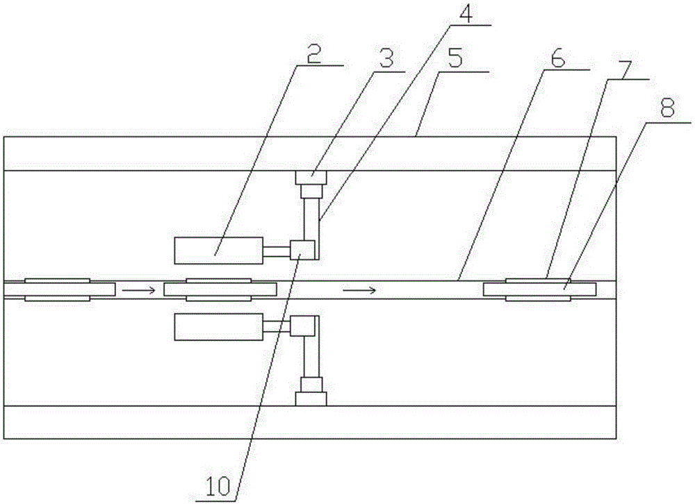
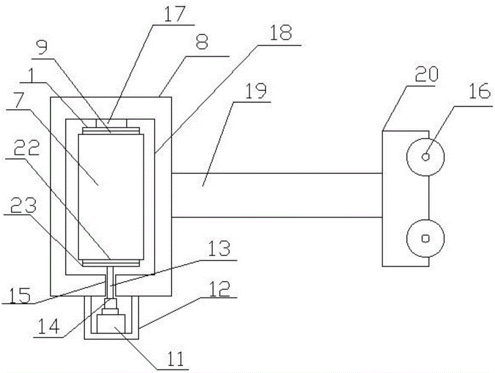
[0018] like figure 1 and figure 2 As shown, a kind of mechanical parts processing and molding system of the present invention includes a casing 5, a fixing device 8 and a processing part 7, and a hydraulic telescopic rod 3 is fixedly installed on both ends of the casing 5, and the hydraulic telescopic rod 3 The telescopic end is fixedly installed with a mounting block 4 through a universal joint with a servo device, and the two mounting blocks are arranged oppositely. The mounting blocks 4 are all fixedly mounted with a first motor 10, and the shaft end of the first motor 10 is fixed A cylindrical grinding block 2 is installed, and the two cy...


PUM


Abstract

The invention discloses a mechanical component machining forming system. The mechanical component machining forming system comprises a shell, a fixing device and a machined component. Each of the two ends in the shell is fixedly provided with a hydraulic telescopic rod. The telescopic end of each hydraulic telescopic rod is fixedly connected with an installing block through a universal joint with a servo device. The two installing blocks are oppositely arranged. Each installing block is fixedly provided with a first motor. A cylindrical grinding block is fixedly arranged at the rotating shaft end of each first motor. The two cylindrical grinding blocks are arranged in a parallel structure manner, and a gap exists between the two cylindrical grinding blocks. A sliding groove is formed in the inner wall of the shell and transversely arranged, one or more sliding blocks are movably arranged in the sliding groove, and the ends, located in the sliding groove, of the sliding blocks are each fixedly provided with one or more wheels. The wheels are driven by a drive device which is a stepping motor. The mechanical component machining forming system is simple in structure, convenient to use and capable of automatically fixing a component needing to be ground, and the grinding speed and efficiency are greatly improved.

Description

technical field [0001] The invention relates to the field of mechanical processing, in particular to a processing and forming system for mechanical parts. Background technique [0002] At present, most of the mechanical parts need to be polished in the last step after rough processing to shape the mechanical parts. The current grinding is generally manual grinding, and small products can be manually polished. For larger products, it is difficult to control the flatness by manual grinding. , it is easy to produce unevenness, the grinding texture is difficult to keep consistent, the requirements for the staff's operating proficiency are high, and the work efficiency is low; in addition, in machining, for some parts with flat surface and regular shape, the surface is relatively smooth. It is difficult to fix during the grinding process, which greatly reduces the speed of grinding. Contents of the invention [0003] In order to solve the above problems, the present invention ...

Claims


Application Information

Patent Timeline
Patent Type & Authority Patents(China)
IPC IPC(8): B24B19/00B24B41/06B24B41/04B24B41/02B24B49/12B24B27/00
CPCB24B19/00B24B27/0076B24B41/02B24B41/04B24B41/06B24B49/12
Inventor 贾建军
Owner XIAN TECH UNIV
Learn More