Constant current driving circuit

A constant current drive and circuit technology, applied in the direction of electrical components, output power conversion devices, etc., can solve the problems of difficult drive current control, long current lag time, complex circuit design, etc., to achieve convenient drive current control, low cost, The effect of simple structure

Inactive Publication Date: 2017-07-28
JIANGSU MODERN POWER CAPACITOR
View PDF3 Cites 0 Cited by
  • Summary
  • Abstract
  • Description
  • Claims
  • Application Information

AI Technical Summary

Problems solved by technology

[0002] With the development of society and the progress of industrial control, industrial automation control has been popularized and widely used in all walks of life, but these control output control parts are still dominated by ordinary switches, which can meet the requirements for occasions with low requirements, but For control occasions with high precision requirements, it is obviously incompetent
At present, the constant current drive circuit is mainly composed of dedicated chips, isolation circuits and protection circuits. The circuit design is complex and the cost is high.
At the same time, the driving current control of the existing constant current driving circuit is relatively difficult, and it is difficult to realize the preset current curve for output, and the current lag time is long

Method used


Image

  • Constant current driving circuit

Examples


Embodiment Construction

[0016] The present invention will be further described in detail below in conjunction with the accompanying drawings and examples. The following examples are explanations of the present invention and the present invention is not limited to the following examples.

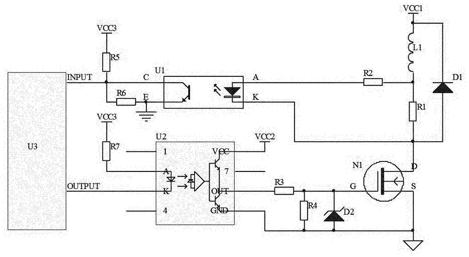
[0017] Such as figure 1 As shown, a constant current driving circuit of the present invention includes a load L1, a sampling resistor R1, a sampling resistor R2, a freewheeling diode D1, a switch tube N1, an isolation chip U1, an isolation chip U2 and a control chip U3, and one end of the load L1 Connect with the load power supply VCC1 and the cathode of the freewheeling diode D1, the other end of the load L1 is connected with one end of the sampling resistor R1 and the sampling resistor R2, the other end of the sampling resistor R2 is connected with the A pin of the isolation chip U1, and the other end of the sampling resistor R1 It is connected to the anode of the freewheeling diode D1, the K pin of the isolation ...


PUM


Abstract

The present invention discloses a constant current driving circuit. One end of a load L1 is connected to a load power source VCC1 and the cathode of a freewheeling diode D1, the other end of the load L1 is connected to one ends of sampling resistors R1 and R2, the other end of the sampling resistor R2 is connected to the A pin of an isolation chip U1, the other end of the sampling resistor R1 is connected with the anode of the freewheeling diode D1, the K pin of the U1 and the drain of a switch N1, the C pin of the U1 is connected with one ends of the resistors R5, R6 and the INPUT terminal of a control chip U3, the other end of the resistor R5 is connected with a power supply VCC3, the other end of the resistor R6 and the E pin of the U1 are grounded, the OUTPUT pin of the control chip U3 and the K pin of the isolation chip U2 are connected, the A pin of an isolated chip U2 is connected with one end of a resistor R7, the other end of the resistor R7 is connected with the power supply VCC3, the VCC pin of the isolation chip U2 is connected with a power supply VCC2, the OUT pin of the isolation chip U2 is connected with the gate of the switch N1, and the GND pin of the isolation chip U2 and the source of the switch N1 are grounded. The structure is simple, the driving current control is convenient, and the cost is low.

Description

technical field [0001] The invention relates to a driving circuit, in particular to a constant current driving circuit. Background technique [0002] With the development of society and the progress of industrial control, industrial automation control has been popularized and widely used in all walks of life, but these control output control parts are still dominated by ordinary switches, which can meet the requirements for occasions with low requirements, but It is obviously incompetent for control occasions with high precision requirements. At present, the constant current driving circuit is mainly composed of a dedicated chip, an isolation circuit and a protection circuit, and the circuit design is complicated and the cost is high. At the same time, it is difficult to control the driving current of the existing constant current driving circuit, it is difficult to realize the preset current curve for output, and the current lag time is long. Contents of the invention ...

Claims


Application Information

Patent Timeline
Patent Type & Authority Applications(China)
IPC IPC(8): H02M1/092
CPCH02M1/092
Inventor 宋玉锋顾曹新孟领刚姚卫东沈卫峰王春华顾明锋丁菊夏文夏武柳振铁纪陈平
Owner JIANGSU MODERN POWER CAPACITOR
Why Eureka
Try Eureka