Virtual-machine dynamic allocation system and server
A dynamic configuration, server technology, applied in transmission systems, instruments, computing, etc., can solve the problem that the response may not be fast
Inactive Publication Date: 2017-07-28
OKI ELECTRIC IND CO LTD
5 Cites 0 Cited by
AI-Extracted Technical Summary
Problems solved by technology
[0012] However, in an environment where the client can connect to multiple slave servers in physical proximity, there is a problem regarding which slave server should execute the application operation.
For examp...
Method used
[0110] Here, the reason for selecting the slave server 20 with high CPU performance will be described. This is because the response of the application is quick because the slave server 20 equipped with a CPU h...
Abstract
A virtual-machine dynamic allocation system and a server are provided. A slave server with an optimal response time with respect to a program can be selected from slave servers located near a client. The virtual-machine dynamic allocation system in which a master server dynamically allocates a virtual machine that is to execute a requested program to any one of slave servers, includes: a response-measurement-time-information measuring unit configured to measure response-time information about a period between transmission of a request signal from each slave server to each of programs operating in the master server and reception of a response signal from each program in the master server; a response-time-information storage unit configured to store the measured response-time information of each program for each slave server; and a slave-server determining unit configured to refer to the response-time-information storage unit so as to determine a slave server that is to execute the requested program.
Application Domain
Program controlTransmission
Technology Topic
Client-sideVirtual machine +2
Image
Examples
- Experimental program(1)
Example Embodiment
[0026] (A) Main implementation
[0027] Hereinafter, implementations of the virtual machine dynamic configuration system and server of the present invention will be described in detail with reference to the accompanying drawings.
[0028] (A-1) Configuration of Embodiment
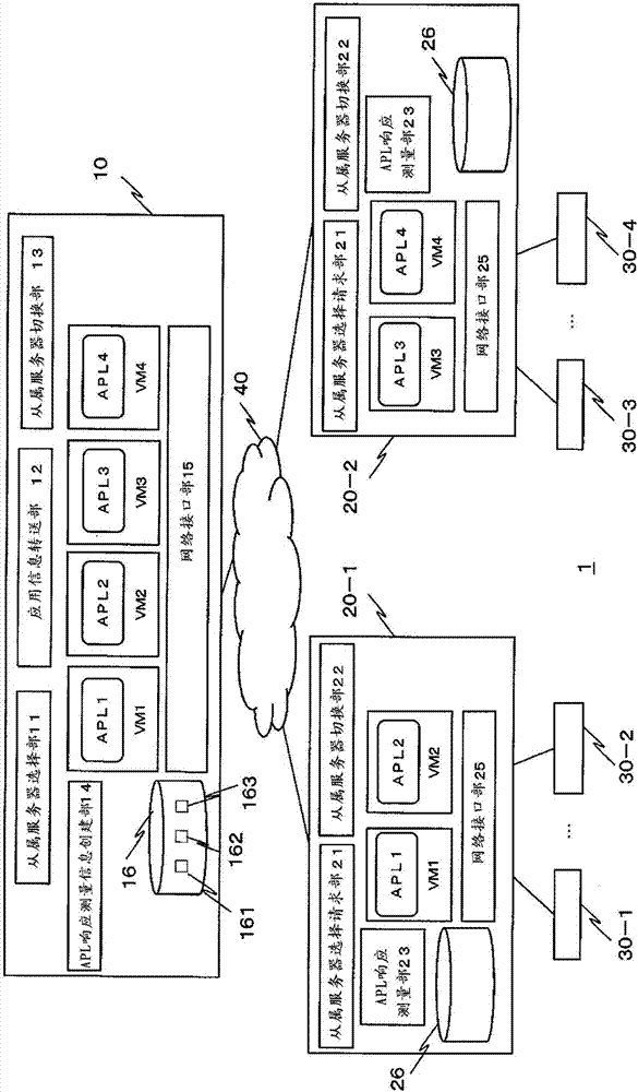
[0029] figure 1 It is an overall configuration diagram showing the overall configuration of the network system according to the embodiment.
[0030] exist figure 1 Among them, the network system 1 of the embodiment has the master server 10, the slave servers 20-1 and 20-2, the clients 30-1 to 30-4, and the network 40.
[0031] In addition, in the following, when explaining the constituent elements common to each of the slave servers 20-1 and 20-2 and each of the clients 30-1 to 30-4, they will be shown as the slave server 20, the client 30 to illustrate. In addition, the number of each of the master server 10, the slave server 20, and the client 30 is not particularly limited.
[0032] exist figure 1 In the network system 1 of the embodiment, a distributed network system is assumed in which a plurality of slave servers (edge servers) 20 located physically close to the client 30 virtually execute application operations in a cloud environment.
[0033] In addition, in the network system 1, the master server 10 and the slave server 20 are equipped with a virtualization environment for constructing a cloud environment. That is, the master server 10 and the slave server 20 have a virtualization environment in which a virtual machine (VM: Virtual Machine) is activated on the OS, and the virtual machine executes an application operation.
[0034] Here, the application (application program) is a software program for performing information processing requested by a user. The application collects data from the client, and performs data statistical processing, data analysis processing, and the like. It is assumed that the application is required to be real-time.
[0035] The application is not particularly limited as long as real-time performance is required. For example, it can be used in traffic control, automobile operation system, business system, various management systems, HEMS (Home Energy Management System), BEMS (Building Energy Management System), FEMS (factory energy management system) and other energy management systems.
[0036] The client 30 requests a desired application operation to the servers on the cloud (the master server 10 and the slave server 20 ).
[0037] Although the hardware configuration of the client 30 is not shown, it has a communication device (for example, short-range wireless communication, wireless communication, wired communication, etc.), CPU, ROM, RAM, input/output interface and other computing processing devices. In addition, the client 30 provides input data (for example, various data such as sensor data) for the application to the server on the cloud, and acquires data obtained by the operation of the application from the server.
[0038] exist figure 1 Among them, the master server 10 has a slave server selection unit 11 , an application information transfer unit 12 , a slave server switching unit 13 , an application response measurement information creation unit 14 , virtual machines (VMs) 1 to 4 , a network interface unit 15 , and a storage unit 16 .
[0039] In addition, although the hardware structure of the main server 30 is not shown in figure, it has CPU, ROM, RAM, EEPROM, an input/output interface part, a communication device, etc. similarly to a general-purpose server. Various functions of the main server 30 are realized by the CPU executing processing programs stored in the ROM. Alternatively, the handler can be created by installation, in which case the handler can be created by figure 1 Each of the constituent modules shown is represented.
[0040] The main server 10 has all the applications that can be provided by the cloud service, and the VM started on the OS executes the application requested by the client 30 (hereinafter, referred to as "APL").
[0041] here at figure 1 In FIG. 2 , it is shown that the VM executes APL in the master server 10 , but actually, the slave server 20 selected by the master server 10 executes the application requested by the client 30 . Therefore, the master server 10 has a function of responding to requests from the client 30 and the slave server 20 .
[0042] The master server 10 selects a slave server 20 placed physically close to the client 30 that is the user, and dynamically places an application on the slave server 20 .
[0043] The network interface unit 15 is a part that transmits and receives information to and from the network 40 by, for example, TCP/IP.
[0044]VM1 to VM4 are virtual machines activated on the OS of the main server 10 . Each VM1-VM4 executes APL1-APL4 requested by the client 30, respectively. Each VM1-VM4 stores the data necessary for execution of each APL1-APL4 in the storage part 16, such as HDD, and executes each APL1-APL4 using the data acquired from the client 30.
[0045] In addition, in figure 1 In the figure, the case where VM1-VM4 respectively executes four APL1-4 is shown. Of course, the number of APLs is not limited, nor is the number of VMs activated to execute each APL.
[0046] The slave server selection unit 11 selects a slave server that executes the application requested by the client 30 among the distributed slave servers 20 .
[0047] That is, when the slave server selection unit 11 receives an inquiry for server selection from the slave server 20 that has acquired an application request (use request) from the client 30, it selects the best one for executing the requested application according to a predetermined server selection method. Slave server 20. In addition, the slave server selection unit 11 instructs the selected slave server 20 to execute the application. Accordingly, it is possible to select the optimal slave server 20 that virtually executes the application requested by the client 30 . In addition, the detailed description of the server selection method by the slave server selection unit 11 will be described in detail in the section of operation.
[0048] The application information transfer unit 12 transfers information necessary for executing the application requested by the client 30 to the slave server 20 selected by the slave server selection unit 11 or the switching destination slave server 20 selected by the slave server switching unit 13 .
[0049] At this time, the application information transfer unit 12 transfers information related to the client 30 which is the request source of the application, designates the type of application requested by the client 30, and executes data required for the execution of the application (for example, data stored in the HDD). etc.) for dynamic configuration of virtual machines. Also, for dynamic allocation of virtual machines, there is no particular limitation on the method of transferring information required for application execution, and various methods can be widely applied.
[0050] The slave server switching unit 13 monitors the application response status of a plurality of slave servers 20 including the slave server 20 executing the application requested by the client 30, and switches to the slave server 20 with the fastest response based on the monitoring result.
[0051] The application response measurement information creation unit 14 creates application response measurement information 161 described later based on the measurement information of the response time of each APL acquired from each slave server 20 .
[0052] The storage unit 16 is a storage area that stores processing programs, applications, data necessary for the applications, and the like. In addition, the storage unit 16 also stores application response measurement information 161 , a CPU performance list 162 , slave server information 163 , and the like.
[0053] The application response measurement information 161 holds measurement information (measurement value) obtained by measuring the response time of each APL of each slave server 20 to a request made by each APL of the master server 10 for each slave server 20 .
[0054] figure 2 It is a configuration diagram showing the configuration of the application response measurement information 161 according to the embodiment.
[0055] like figure 2 As shown, the application response measurement information 161 has "server identification information" and "application response measurement value" as items. In addition, the items are not limited to these.
[0056] The application response measurement information 161 is the response time for each application. When measuring the response time of each of a plurality of applications, the application response measurement information 161 is created for each application.
[0057] In addition, in figure 2 In , a case where one application response measurement value is listed for each slave server 20 is exemplified. However, since the slave server selection unit 11 and the slave server switching unit 13 periodically measure the response time, the application response measurement information 161 may hold the response time that changes over time for each slave server 20 .
[0058] exist figure 2 Among them, "server identification information" is a part that describes the identification information of the slave server 20, for example, the name of the slave server 20, the IP address of the slave server 20, and the like are described.
[0059] The "application response measurement value" is the response time (round-trip delay time of application response) until each APL of each slave 20 receives a request sent from each APL of each slave server 20 to each APL of the master server 10 . The application response measurement value is a measurement result of each slave server 20 , and the result acquired from each slave server 20 is held in the application response measurement information 161 .
[0060] The application response measurement is not the round-trip delay time on the network of the underlying layer (eg, physical layer, network layer, etc.), but is intended to include the response time of the layer of the application layer.
[0061] This is because the quick response required by the client 30 is the short response time for the execution action of the application. In the measurement of the round-trip delay time of the lower layer, there are cases where the real-time performance of the application cannot be sufficiently ensured. In addition, even when the slave server 20 physically close to the client 30 operates the application, the response of the application may not necessarily be fast.
[0062] Therefore, in this embodiment, in order to select the slave server 20 whose application response is fast, the response time of an application (the round-trip delay time of an application) is measured.
[0063] The CPU performance list 162 holds the performance of the CPU mounted in each slave server 20 for each slave server 20 .
[0064] image 3 It is a configuration diagram showing the configuration of the CPU performance list 162 according to the embodiment.
[0065] exist image 3 Among them, the CPU performance list 162 has "server identification information" and "CPU performance" as items. In addition, the items are not limited to these.
[0066] The “CPU performance” is performance information of a CPU mounted in each slave server 20 . For example, in image 3 In , "aaaaxxx-3000(2.6GHz)" indicates the model of the CPU. That is, it indicates that the manufacturer name of the CPU is "aaaa", the CPU name is "xxx", the model number is "3000", and the number of clocks is "2.6GHz". In this way, the CPU performance may be information on the model of the CPU, or may be a relative evaluation value that relatively evaluates the CPU performance corresponding to the CPU level (for example, a relative evaluation value when evaluating the CPU performance in five levels, etc. ).
[0067] In addition, the information related to the CPU performance of each slave server 20 may also be information obtained through data packet exchange between the master server 10 and the slave server 20, and may also be information that can identify the CPU performance of the slave server 20 in advance. pre-set information.
[0068] The slave server information 163 holds information such as address information (IP address, etc.) and location information (for example, latitude and longitude, location information at the time of physical arrangement, etc.) of the slave server 20 . In addition, the slave server information holds information in which each slave server 20 is associated with the type of application executed by each slave server 20 .
[0069] exist figure 1 Among them, the slave server 20 has a slave server selection request unit 21 , a slave server switching unit 22 , an application response measurement unit 23 , a VM, a network interface unit 25 , and a storage unit 26 .
[0070] In addition, although the hardware structure of the slave server 20 is not shown in figure, it has CPU, ROM, RAM, EEPROM, an input/output interface part, a communication device, etc. similarly to a general-purpose server. Various functions of the slave server 20 are realized by the CPU executing processing programs stored in the ROM. In addition, it is also possible to build by installing a handler, and even in this case, the handler can be built by figure 1 Each of the constituent modules shown is represented.
[0071] The slave server 20 is a server arranged at a location physically close to the client 30 side. The slave server 20 is a server instructed by the master server 10 to execute an application requested by the client 30, acquires data from the client 30, and executes the application operation.
[0072] For example, VM1 of the slave server 20-1 executes APL1, and VM2 executes APL2. Also, VM3 of the slave server 20-2 executes APL3, and VM4 executes APL4.
[0073] The network interface unit 25 is a part for transmitting and receiving information with the client 30 or with the main server 10 .
[0074] For example, information may be transmitted and received between the network interface unit 25 and the client 30 by short-range wireless communication. In addition, information based on TCP/IP may be transmitted and received between the network interface unit 25 and the main server 10 .
[0075] VM1 to VM4 are virtual machines instructed by the host server 10 to execute respective APL1 to APL4 requested by the client 30 on the OS.
[0076] The slave server selection request unit 21 makes a request to the master server 10 to select a slave server 20 that executes the application, upon receiving a request to use the application from the client 30 .
[0077] The slave server switching request unit 22 periodically inquires of the master server 10 whether switching to another slave server 20 is necessary.
[0078] Each APL transmits a request including dummy information to each APL of the main server 10, and the application response measurement unit 23 measures the response time to the request. The application response measurement unit 23 periodically measures the response time of each APL. In addition, the application response measurement unit 23 transmits the measured response time of each APL to the main server 10 .
[0079] The storage unit 26 is a storage area that stores processing programs, applications, data necessary for the applications, and the like.
[0080] (A-2) Operation of Embodiment
[0081] Next, the operation of the method for dynamically configuring applications in the network system 1 according to the embodiment will be described in detail with reference to the drawings.
[0082] (A-2-1) Action of creating application response measurement information list
[0083] Figure 4 It is a sequence diagram showing the operation of the creation process of the application response measurement information list according to the embodiment.
[0084] For example, the applications that can be executed by the main server 10 on the cloud include APL1 to APL4.
[0085] In order to notify the types of executable applications, the master server 10 always notifies each slave server 20 that the master server 10 operates APL1 to APL4 ( S11 ).
[0086] The notification method is not particularly limited, and can be realized, for example, by the master server 10 notifying each slave server 20 of a packet including list information describing APL1 to APL4 indicating types of executable applications.
[0087]In each slave server 20, the application response measurement unit 23 periodically transmits a request including dummy information to each of APL1 to APL4 of the master server 10 (S12).
[0088] Here, the content of the dummy information may also vary depending on the type of application.
[0089] For example, when the application is SIP, the application of each slave server 20 may use the Invite message of SIP to transmit dummy information in which the content of the message is empty (for example, all zeros, etc.).
[0090] Also, for example, the application of each slave server 20 may transmit dummy information including data to which the application of the master server 10 has not responded (that is, meaningless data).
[0091] More specifically, information used when assembling the printed circuit board mounted on the slave server 20 may be preset and used as dummy information. For example, when assembling a printed circuit board mounted on the slave server 20, barcode information read from a printed circuit board assembly machine may be used as dummy information. The barcode information for assembling printed circuit boards includes a barcode number, a work start flag or a work end mark for assembling printed circuit boards, and the like. The slave server 20 transmits, for example, barcode read information (information including a barcode number and a work start flag) as dummy information to the APL of the master server 10 . At this time, since the APL of the main server 10 is unregistered information, the APL of the main server 10 responds with an error.
[0092] When each APL1-APL4 of the master server 10 receives the request including the dummy information of each slave server 20, it will reply the response information to this request (S13). That is, in the main server 10, errors occur in each of the APL1 to APL4 which received the request including the dummy information. Therefore, an error response is returned to the APL of each slave server 20 .
[0093] In each slave server 20, the application response measurement unit 23 manages the transmission time of the request including dummy information and the reception time of the error response, and measures application response measurement information based on the difference between the transmission time and the reception time (S14).
[0094] Also, each slave server 20 transmits information including application response measurement information and information on its own CPU performance to the master server 10 ( S15 ). In addition, when each slave server 20 has already transmitted the information on the CPU performance to the master server 10 , it is also possible not to transmit the information on the CPU performance to the master server 10 thereafter.
[0095] In the master server 10 , the application response measurement information creation unit 14 stores the application response measurement information received from each slave server 20 in the application response measurement information 161 . Also, in the master server 10 , the application response measurement information creation unit 14 stores information on the CPU performance of the slave server 20 received from each slave server 20 in the CPU performance list 162 ( S16 ).
[0096] Each of the slave servers 20 and the master server 10 periodically performs the processes of S12 to S16.
[0097] (A-2-2) Selection operation of the slave server 20
[0098] First, use Figure 5 The selection operation of the slave server 20 when the client 30 makes a request to use an application will be described.
[0099] Figure 5 It is a sequence diagram showing selection processing of the slave server 20 in the embodiment.
[0100] The client 30 makes a request to use the APL1 to the slave server 20-1 (S101).
[0101] The slave server 20-1 transmits to the master server 10 a selection request of the slave server 20 that executes the APL1 requested by the client 30 (S102).
[0102] In the master server 10, the slave server selection unit 11 measures the response time of each application in each slave server 20, and based on the measurement result, selects the slave server 20 that executes the APL1 requested by the client 30 (S103).
[0103] Image 6 It is a flowchart showing the selection process of the slave server executing the application requested by the client 30 according to the embodiment.
[0104] First, in the master server 10, the slave server selection unit 11 refers to the application response measurement information 161, and compares the response measurement values of the respective APL1 to APL4 in the respective slave servers 20 (S201).
[0105] At this time, the application response measurement information 161 holds the application response measurement value of each slave server 20 for each APL. Therefore, the slave server selection unit 11 compares the application response measurement values of the respective slave servers 20 with respect to the APL requested by the client 30 .
[0106] The slave server selection unit 11 selects the smallest application response measurement value, and selects the slave server 20 having the smallest application response measurement value (S203).
[0107] Here, the slave server selection unit 11 selects the slave server 20 with the smallest application response measurement value, but there may be cases where the difference between the minimum value of the application response measurement value and other values is small and the selection of the optimal slave server 20 may be insufficient. Happening. Therefore, in the embodiment, when there are a plurality of minimum values and other values within a predetermined range in ascending order of application response measurement values, the process proceeds to S204.
[0108] The slave server selection unit 11 refers to the CPU performance list 163, and compares the CPU performances of the corresponding slave servers 20 when there are a plurality of values other than the minimum value within a predetermined range (S204).
[0109] Then, when there is a difference in the CPU performance of the plurality of slave servers 20 (S204), the slave server 20 with high CPU performance is selected (S205).
[0110] Here, the reason for selecting the slave server 20 with high CPU performance will be described. This is because the response of the application is fast because the slave server 20 equipped with a CPU having a high CPU performance has a high processing capability. For example, selection of the slave server 20 and the like are considered in consideration of the processing load of the CPU at the present moment.
[0111] However, with the advancement of CPU technology in recent years, the processing capability of the CPU has also become extremely high. Therefore, even if the processing load of the CPU is currently high, the response time of the application tends to be accelerated as time passes when the CPU performance is high.
[0112] Therefore, in the present embodiment, when there are slave servers 20 having the same application response measurement value (that is, within a predetermined range), the slave server selection unit 11 selects the slave server 20 with high CPU performance.
[0113] In S204, when there is no difference in the CPU performance of the plurality of slave servers 20, the slave server 20 with the smaller application ID is selected (S206). That is, as the slave server 20 executing the APL requested by the client 30, the slave server 20 allocated before (already) is selected.
[0114] back to Figure 5 In S103, the selection process of the slave server 20 will be described.
[0115] In S103, the slave server selection unit 11 selects the slave server 20-1 as the server executing the APL1 requested by the client 30. In this way, the master server 10 transmits a slave server selection instruction to the slave server 20-1 (S104).
[0116] Also, the master server 10 transfers the APL1 requested by the client 20, data necessary for execution of the application, and the like to the slave server 20-1.
[0117] The slave server 20-1 transmits a slave server selection instruction to notify the client 30 that the server executing APL1 is a slave server (S105).
[0118] Thereafter, the client 30 transmits data necessary for the operation of the APL1 to the slave server 20-1, and starts using the APL1 (S106).
[0119] (A-2-3) Switching method of slave server 20 (Part 1)
[0120] Next, use Figure 7 The processing operation of the slave server 20-directed slave server 20 switching method performed by the slave server 20 will be described.
[0121] Figure 7 It is a sequence showing the operation of the switching process of the slave server 20 according to the embodiment.
[0122] Here, the slave server 20-1 executes the application requested by the client 30.
[0123] The client 30 transmits a message (message including data) necessary for the execution of the application to the slave server 20-1 (S301).
[0124] In the slave server 20 - 1 , the slave server switching unit 22 counts the number of times of reception of messages from the client 30 . Then, when the number of messages received from the client 30 reaches a predetermined number of times (for example, 10 times), the slave server switching unit 23 sends a slave server selection request to the master server 10 to inquire about an optimal slave server 20 (S302, S303).
[0125] In the master server 10, the slave server selection unit 11 refers to the application response measurement information 161, and selects the slave server 20-2 that executes the APL1 requested by the client 30 (S304). here at Figure 7 The S304, carried out using the Image 6 The selection process of the slave server 20. Also, omit Image 6 Detailed description of the selection process of the slave server 20.
[0126] After that, the slave server selection section 11 selects the slave server 20 - 2 as the server that executes the APL1 requested by the client 30 . In this way, the master server 10 transmits a slave server selection instruction to the slave server 20-1 (S305). That is, the master server 10 transmits to the slave server 20-1 a slave server selection instruction indicating that the switching destination of the APL1 requested by the execution client 30 is "the slave server 20-2".
[0127] Also, in the master server 10, the application information transfer unit 12 transfers the APL1 requested by the client 20, data necessary for execution of the application, and the like to the slave server 20-2 (S306).
[0128] The slave server 20-1 transmits a slave server selection instruction to the client 30 in order to inform the client 30 that the server executing APL1 is the slave server 20-2 (S307).
[0129] Thereafter, the client 30 transmits data necessary for the operation of the APL1 to the slave server 20-2, and starts using the APL1 (S308).
[0130] (A-2-4) Switching method of slave server 20 (Part 2)
[0131] Next, use Figure 8 The processing operation of the master server 10 instructing the slave server 20 to switch the slave server 20 will be described.
[0132] Figure 8It is a sequence showing the operation of the switching process of the slave server 20 according to the embodiment.
[0133] Here, the slave server 20-1 executes the application requested by the client 30.
[0134] In the master server 10, the slave server switching unit 13 periodically (for example, every minute, every several minutes) inquires about the application response measurement information to each of the slave servers 20-1 to 20-2. Each APL1 to APL4 of each slave server 20-1 to 20-2 sends a request including dummy information to each APL of the master server 10, measures the response time until receiving a response, and transmits the response measurement information to the master server 10 (S401~S404).
[0135] In the master server 10, the slave server selection unit 11 refers to the application response measurement information 161, and selects the slave server 20-2 that executes the APL1 requested by the client 30 (S405). here at Figure 8 The S405, carried out using the Image 6 The selection process of the slave server 20. Also, omit Image 6 Detailed description of the selection process of the slave server 20.
[0136] In addition, the client 30 transmits a message (message including data) required for execution of the application to the slave server 20-1 until the slave server 20 is switched (S406).
[0137] Thereafter, the slave server selection unit 11 selects the slave server 20-2 as the server executing the APL1 requested by the client 30. In this way, the master server 10 transmits a slave server selection instruction to the slave server 20-1 (S407). That is, the master server 10 transmits to the slave server 20-1 a slave server selection instruction indicating that the switching destination of the APL1 requested by the execution client 30 is "the slave server 20-2".
[0138] Also, in the master server 10, the application information transfer unit 12 transfers the APL1 requested by the client 20, data necessary for execution of the application, and the like to the slave server 20-2 (S408).
[0139] The slave server 20-1 transmits a slave server selection instruction to the client 30 in order to inform the client 30 that the server executing APL1 is the slave server 20-2 (S409).
[0140] Thereafter, the client 30 transmits data necessary for the operation of the APL1 to the slave server 20-2, and starts using the APL1 (S410).
[0141] (A-3) Effects of Embodiment
[0142] As described above, according to the present embodiment, even when there are a plurality of slave servers physically close to the client, it is possible to dynamically configure the position of the virtual machine executing the application requested by the client. As a result, the response time of the application operation can be significantly improved.
PUM


Description & Claims & Application Information
We can also present the details of the Description, Claims and Application information to help users get a comprehensive understanding of the technical details of the patent, such as background art, summary of invention, brief description of drawings, description of embodiments, and other original content. On the other hand, users can also determine the specific scope of protection of the technology through the list of claims; as well as understand the changes in the life cycle of the technology with the presentation of the patent timeline. Login to view more.