Method for operating combustion engine

A technology of internal combustion engine, working, applied in the direction of internal combustion piston engine, combustion engine, starting of engine

Inactive Publication Date: 2017-08-01
ROBERT BOSCH GMBH
View PDF8 Cites 0 Cited by
  • Summary
  • Abstract
  • Description
  • Claims
  • Application Information

AI Technical Summary

Problems solved by technology

This problem occurs every time I start

Method used


Image

  • Method for operating combustion engine
  • Method for operating combustion engine
  • Method for operating combustion engine

Examples


Embodiment Construction

[0026] The invention is schematically illustrated in the drawings with the aid of embodiments and will be described in more detail below with reference to the drawings.

[0027] It should be noted that for future start-up methods with targeted decompression, a certain stop (abstelle) position must be provided and the point in time at which the inlet is closed must be shifted.

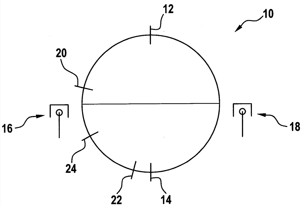
[0028] figure 1 A working cycle with top dead center OT 12 and bottom dead center UT 14 is shown in diagram 10 . Also shown are cylinder 1 , reference number 16 , and cylinder 0 , reference number 18 . Furthermore, the instant 20 of the closing of the inlet 20 and the first synchronous instant S0 22 and the second synchronous instant S1 24 are plotted.

[0029] Usually, the engine is in the figure 1 The position shown in , where cylinder 0 18 is on the expansion stroke and cylinder 1 16 is on the compression stroke.

[0030] When starting is requested, the crankshaft begins to turn, regardless of th...


PUM


Abstract

The invention relates to a method and an arrangement for operating a combustion engine with a number of cylinders (16, 18), in which at least one of the cylinders (16, 18) is subjected to a calculation of an air filling degree. Whether the cylinder (16, 18) is closed is checked before the air filling degree is calculated.

Description

technical field [0001] The invention relates to a method for operating an internal combustion engine and a device for carrying out the method. Background technique [0002] The internal combustion engine is used in vehicles for propulsion and for this purpose converts the chemical energy of the fuel into mechanical work. For this purpose, the fuel or fuel-air mixture is combusted in combustion chambers, ie cylinders of the internal combustion engine. To control the internal combustion engine, a controller, typically an electric motor controller, is usually provided. The controller evaluates the received signals and controls the internal combustion engine taking into account the information transmitted with these signals. [0003] An important parameter for the operation of an internal combustion engine is the so-called air fill level, which indicates how much air is in the cylinder. Also relevant here is how much fuel has to be introduced into the cylinder. The degree of...

Claims


Application Information

Patent Timeline
Patent Type & Authority Applications(China)
IPC IPC(8): F02D41/06F02D41/18
CPCF02D41/008F02D41/062F02D41/18F02D41/0002F02D41/009F02D41/06F02D2041/0092F02D2200/0402F02D2200/0411F02N11/0814Y02T10/40
Inventor A.施密特M.魏因曼S.乌尔T.鲍曼Y.泽米施
Owner ROBERT BOSCH GMBH
Why Eureka
Try Eureka