
Adjustable gas nozzle structure

A technology of gas adjustment and nozzle, which is applied in the direction of combustion engine, internal combustion piston engine, oil supply device, etc., can solve the problem of small contact area between gas and combustion chamber, and achieve the effect of increasing the degree of scattering and uniformity of gas

Inactive Publication Date: 2017-08-01
SICHUAN SENJIE GAS EQUIP CO LTD
View PDF7 Cites 0 Cited by
  • Summary
  • Abstract
  • Description
  • Claims
  • Application Information

AI Technical Summary

Problems solved by technology

[0005] The purpose of the present invention is to provide a gas-adjustable nozzle structure, realize the purpose of a gas nozzle with adjustable direction, and solve the problem in the prior art that the contact area between the gas and the combustion chamber is small

Method used


Image

  • Adjustable gas nozzle structure
  • Adjustable gas nozzle structure

Examples


Embodiment

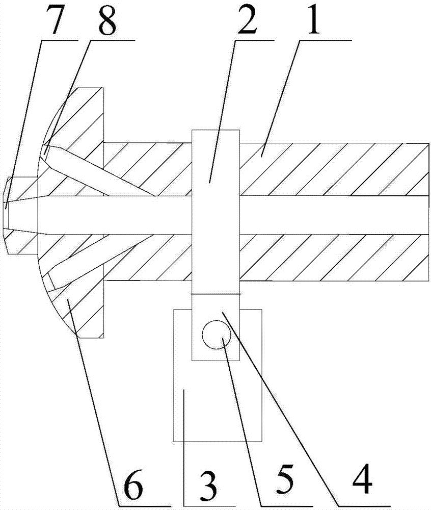
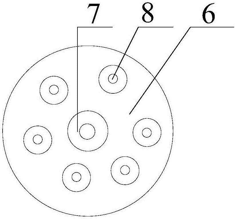
[0021] Such as figure 1 , 2 As shown, a fuel gas adjustable nozzle structure of the present invention includes a nozzle pipe 1, and a fixed ring 2 is sleeved on the outside of the nozzle pipe 1. The inner diameter of the fixed ring 2 is interference fit with the outside of the nozzle pipe 1. The lower end of 1 is also provided with a cylindrical support platform 3, and a connecting block 4 is fixed on the circumferential direction of the fixed ring 2, and a groove is opened in the connecting block 4, and the two ends of the groove clamp the cylindrical The end of the cylindrical support platform 3 is connected with the cylindrical support platform 3 through the rotating shaft 5, and the axis of the rotating shaft 5 is perpendicular to the centerline of the cylindrical support platform 3. One end of the spray pipe 1 is also provided with a nozzle mechanism, the nozzle mechanism includes an annular injection plate 6, a main nozzle 7 is arranged in the middle part of the annular...


PUM


Abstract

The invention discloses an adjustable gas nozzle structure. The adjustable gas nozzle structure comprises a spraying pipe; the outer side of the spraying pipe is sleeved with a fixed ring; the inner diameter of the fixed ring is in interference fit with the outer side of the spraying pipe; a cylindrical support table is arranged at the lower end of the spraying pipe; the peripheral direction of the fixed ring is fixed with a connecting block; a groove is formed in the connecting block; two ends of the groove are clamped with the end parts of the cylindrical support table, and are connected with the cylindrical support table through rotating shafts; and the axis of the rotating shafts is perpendicular to the center line of the cylindrical support table. The adjustable gas nozzle structure realizes the purpose of a gas nozzle capable of adjusting the direction, and solves the problem of smaller contact area between gas and a combustion chamber in the prior art.

Description

technical field [0001] The invention relates to the field of engine gas supply, in particular to a gas-adjustable nozzle structure. Background technique [0002] An engine is a machine that can convert other forms of energy into mechanical energy, including internal combustion engines, external combustion engines, electric motors, etc. For example, internal combustion engines usually convert chemical energy into mechanical energy. The engine is not only applicable to the power generation device, but also refers to the whole machine including the power device (such as: gasoline engine, aero engine). [0003] The injection time has a great influence on the power, economy and stability of the engine. The existing technology is to give the engine an injection advance angle at a given speed to increase the concentration of fresh charge entering the cylinder. , in order to achieve the fastest heat release rate and short combustion cycle. [0004] However, this also leads to une...

Claims


Application Information

Patent Timeline
Patent Type & Authority Applications(China)
IPC IPC(8): F02M21/02
CPCF02M21/0248Y02T10/30
Inventor 何松龙
Owner SICHUAN SENJIE GAS EQUIP CO LTD
Learn More