Converter valve steady-state operation test device using capacitor to bear bias voltage and converter valve steady-state operation test method thereof

A technology of bias voltage and steady-state operation, applied in the direction of measuring devices, measuring electricity, measuring electrical variables, etc., can solve the problems of increasing test cost, complicated control, and system asymmetry, and achieve the effect of simple and reliable main circuit

Active Publication Date: 2017-08-01
RONGXIN HUIKO ELECTRIC TECH CO LTD
View PDF13 Cites 6 Cited by
  • Summary
  • Abstract
  • Description
  • Claims
  • Application Information

AI Technical Summary

Problems solved by technology

[0005] The method in the Chinese patent "A flexible DC transmission voltage source converter valve operation test device" with the publication number CN105372586A requires an additional high-voltage DC rectifier power supply and an additional energy-supplementing bridge arm, which significantly increases the cost of the test device , and because the system is asymmetric, the control is complex
[0006] The Chinese patent "A MMC Converter Valve Steady-state Operation Test Circuit and Its Control Method" with the publication number CN106546852A requires two additional flexible straight bridge arms for energy supplementation, and also requires a high-voltage DC rectifier power supply for power supply, obviously increased testing costs

Method used


Image

  • Converter valve steady-state operation test device using capacitor to bear bias voltage and converter valve steady-state operation test method thereof
  • Converter valve steady-state operation test device using capacitor to bear bias voltage and converter valve steady-state operation test method thereof
  • Converter valve steady-state operation test device using capacitor to bear bias voltage and converter valve steady-state operation test method thereof

Examples


Embodiment Construction

[0039] The specific embodiments provided by the present invention will be described in detail below in conjunction with the accompanying drawings.

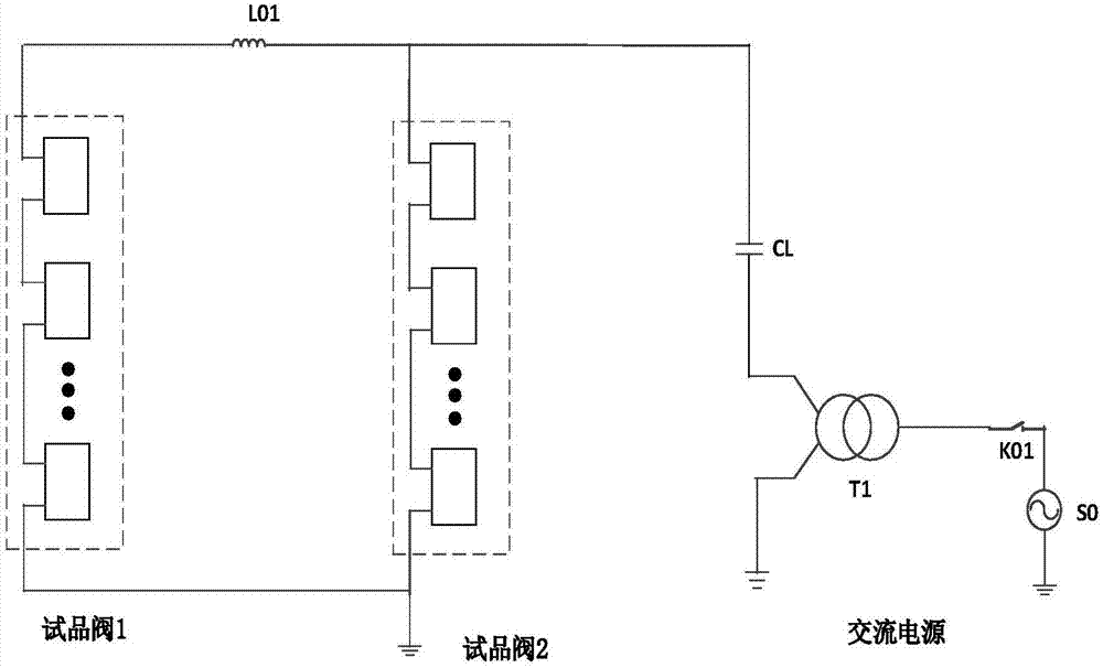
[0040] Such as figure 1 As shown, the steady-state operation test device of the converter valve adopts the capacitor to bear the bias voltage, including the test valve 1, the test valve 2, the capacitor CL, the transformer T1, the circulating current suppression reactance L01, the switch K01 and the AC test power supply S0.

[0041] One end of the sample valve 1 and sample valve 2 is connected and grounded, and the other end is respectively connected to both sides of the circulating current suppressing reactance L01. After the secondary winding of the transformer T1 is connected in series with the capacitor CL, one end is grounded, and the other end is connected to the circulating current suppressing reactance At either end of L01, the primary winding of transformer T1 is connected in series with switch K01 and then connected to A...


PUM


Abstract

The invention provides a converter valve steady-state operation test device using a capacitor to bear bias voltage and a converter valve steady-state operation test method thereof. The device comprises a test valve 1, a test valve 2, a capacitor CL, a transformer T1, a circulating current restraining reactor L01, a switch K01 and an AC test power supply S0. One end of the test valve 1 and one end of the test valve 2 are connected and grounded, and the other end of the test valve 1 and the other end of the test valve 2 are respectively connected with the two sides of the circulating current restraining reactor L01. The secondary winding of the transformer T1 is connected in series with the capacitor CL and then one end is grounded and the other end is connected with any end of the circulating current restraining reactor L01. The primary winding of the transformer T1 is connected in series with the switch K01 and then connected with the AC test power supply S0. A DC voltage component between the converter valve ends is borne by using the capacitor connected in series in the loop, and charging and energy supplementing are performed on the test system by depending on the common transformer without configuring a DC power supply or additionally arranging an energy supplementing valve. A low-power single-phase transformer can be simply used as the transformer or a voltage regulator can be used as the transformer so that the main loop is simple and reliable.

Description

technical field [0001] The invention relates to the technical fields of flexible direct current transmission and power electronics applications, in particular to a device and method for a steady-state operation test of a converter valve that adopts a capacitor to undertake a bias voltage. Background technique [0002] The flexible DC transmission system based on the MMC voltage source converter has excellent performances such as power supply to passive systems or weak AC systems, fast independent control of active power and reactive power, easy construction of multi-terminal networks and environmental friendliness, and the transmission voltage of MMC-HVDC systems The harmonic content is extremely low, and there is no need to configure additional filters, which makes the MMC-based flexible DC transmission have broad application prospects in the field of power transmission. The power unit module, the core component of MMC-HVDC, is the smallest unit of the entire flexible HVDC ...

Claims


Application Information

Patent Timeline
Patent Type & Authority Applications(China)
IPC IPC(8): G01R31/00
CPCG01R31/00Y02E60/60
Inventor 张海涛翁海清王国强易荣岳伟廖其艳
Owner RONGXIN HUIKO ELECTRIC TECH CO LTD
Why Eureka
Try Eureka