Analog timepiece and control method of analog timepiece

一种模拟电子、钟表的技术,应用在电动发电机控制、钟表、交流电动机角单轴角速度控制等方向,能够解决很难判定转子、无法控制转子、无法确保步进电机自由振动等问题,达到缩短时间的效果

Active Publication Date: 2017-08-01
SEIKO INSTR INC
View PDF7 Cites 7 Cited by
  • Summary
  • Abstract
  • Description
  • Claims
  • Application Information

AI Technical Summary

Problems solved by technology

[0007] However, in the two-coil motor described in the above-mentioned Patent Document 1, since the pulse having a braking effect is output after the pulse for driving the rotor is output, the rotor cannot be freely vibrated to generate an induced voltage in the coil.
Therefore, it is difficult to determine whether the rotor has rotated in unit steps
Therefore, in conventional analog electronic timepieces, it may not be possible to ensure the free vibration of the rotor of the stepping motor per unit step, and it may be difficult to reliably detect the induced voltage of the coil, and it may not be possible to reliably control the stepping motor according to the unit step. rotor

Method used


Image

  • Analog timepiece and control method of analog timepiece
  • Analog timepiece and control method of analog timepiece
  • Analog timepiece and control method of analog timepiece

Examples


Embodiment approach

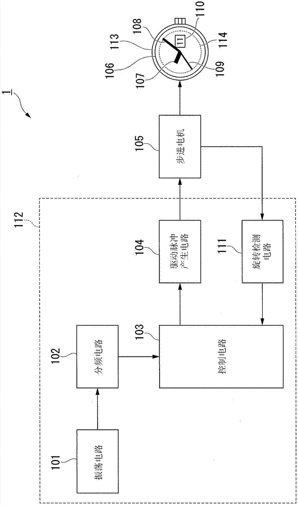
[0052] figure 1 It is a block diagram showing the analog electronic timepiece of the embodiment.

[0053] Such as figure 1 As shown, the analog electronic timepiece 1 has an oscillation circuit 101 , a frequency division circuit 102 , a control circuit 103 , a drive pulse generation circuit 104 , a stepping motor 105 , a rotation detection circuit 111 , a wheel train not shown, and an analog display unit 106 .

[0054] The oscillation circuit 101 generates a signal of a predetermined frequency.

[0055] The frequency dividing circuit 102 divides the frequency of the signal generated by the oscillation circuit 101 to generate a clock signal as a timing reference.

[0056] The control circuit 103 performs control of each electronic circuit element constituting the analog electronic timepiece 1 and control of a pulse signal for driving the motor to rotate.

[0057] The drive pulse generating circuit 104 outputs a pulse signal for driving the motor in rotation based on a contro...


PUM


Abstract

The invention provides an analog timepiece and a control method of the analog timepiece, thereby reliably controlling rotation of a rotor in one unit step. There is provided an analog timepiece including an hour hand, a minute hand, and a second hand which are rotated by a unit step operation of a stepping motor (105). The analog timepiece includes a rotor (30) that rotates the hour hand, the minute hand, and the second hand, and that has a magnetic polarity, a stator (20) that includes magnetic pole portions (20A-20C) disposed around the rotor (30), coils (50A, 50B) that excite the magnetic pole portions (20A-20C), and a control unit that controls each unit step of the rotor (30) in accordance with each pulse group by applying a pulse group including a rotary pulse for rotating the rotor (30) and a braking pulse for braking rotation of the rotor (30), which is applied before the rotary pulse is applied, to the coil (50A, 50B).

Description

technical field [0001] The invention relates to an analog electronic clock and a control method for the analog electronic clock. Background technique [0002] Conventionally, a stepping motor for moving hands such as an hour hand, a minute hand, and a second hand has been used in analog electronic timepieces. In an analog electronic timepiece, it is desirable to reverse the rotation of the hands by advancing them. In the case where the stepper motor can be reversed by dialing the speed, it is necessary to reduce the holding torque of the rotor. However, in the case of a stepping motor having a one-coil structure, a step-out tends to occur due to a reduction in holding torque. [0003] As a stepping motor capable of being reversed by dialing it up, for example, as described in Patent Document 1, there is a stepping motor (hereinafter referred to as "two-coil motor") having a stator having three magnetic pole portions and two coils. Generally speaking, compared with the ab...

Claims


Application Information

Patent Timeline
Patent Type & Authority Applications(China)
IPC IPC(8): G04C3/14G04C10/00
CPCG04C3/14G04C10/00G04C3/143H02P8/02H02P8/22H02K1/12H02K1/2706H02K3/28H02K7/14H02P23/16
Inventor 山本幸祐
Owner SEIKO INSTR INC
Why Eureka
Try Eureka