Method for manufacturing steel pipe and press mold used in said method

A manufacturing method and stamping die technology, applied in the field of steel pipe manufacturing and stamping dies used therein, capable of solving problems such as deterioration of roundness

Active Publication Date: 2017-08-01
JFE STEEL CORP
View PDF13 Cites 8 Cited by
  • Summary
  • Abstract
  • Description
  • Claims
  • Application Information

AI Technical Summary

Problems solved by technology

In addition, in this method, if you want to deform into the desired shape at one time, the deformation will be concentrated locally and the roundness may deteriorate. Therefore, multiple deformations are necessary, and there is a limit to efficient manufacturing.

Method used


Image

  • Method for manufacturing steel pipe and press mold used in said method
  • Method for manufacturing steel pipe and press mold used in said method
  • Method for manufacturing steel pipe and press mold used in said method

Examples


Embodiment 1

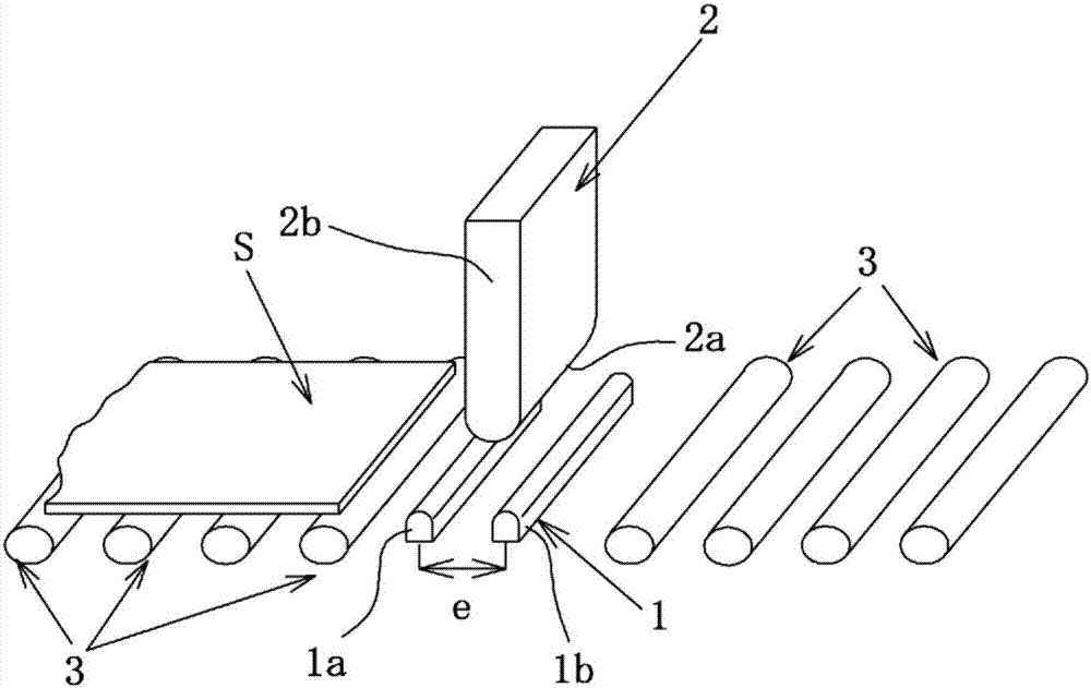
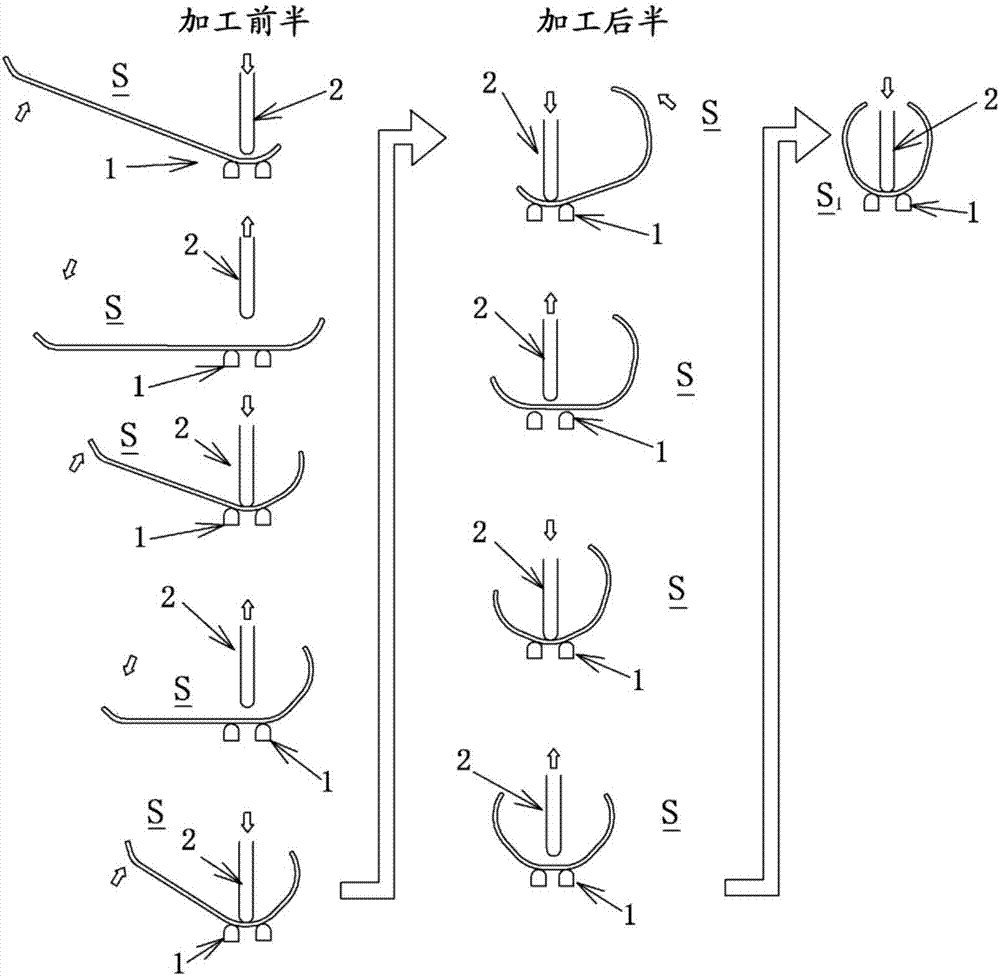
[0110] In order to form a steel pipe with a diameter of 36 inches using a steel plate for linepipes (API grade X60) with a thickness of 38.1mm and a width of 2711mm, it is placed on a die with a distance of 450mm between rod-shaped parts, and a steel pipe with a radius of 308mm processing surface punch, from the position 1120mm away from the width center of the sheet, make the sheet feeding pitch 224mm, press 11 times (5 times from the right end of the paper, 5 times from the left end) to perform 3-point bending bending processing. At this time, the amount of pressing is such that the front end of the punch reaches a position of 15.8 mm from the line connecting the uppermost parts of the rod-shaped member, and bends 30° at a time, but at a position 672 mm from the center of the width of the plate (the third from the right end) times, the third feed from the left end) No pressing is performed, and an unprocessed part is formed at a position of 571 to 795 mm. Next, the molded b...

Embodiment 2

[0114] As in Example 1, in order to form a steel pipe with a diameter of 36 inches using a steel plate for linepipes (API grade X60) with a thickness of 38.1 mm and a width of 2711 mm, it is placed on a die whose interval between rod-shaped members is set to 450 mm Above, using a punch with a processing surface with a radius of 308mm, from a position 1120mm away from the center of the width of the sheet, make the feeding interval of the sheet 224mm, and the number of pressings is 11 times (5 times from the right end of the paper, and 5 times from the left end) 5 times) to perform a bending process of 30° once based on 3-point bending. At this time, the amount of pressing is such that the front end of the punch reaches a position of 15.8 mm from the line connecting the uppermost parts of the rod-shaped member, and bends 30° at a time, but at a position 672 mm from the center of the width of the plate (the third from the right end) time, the third feed from the left end), reduce...

Embodiment 3

[0119] In order to form a steel pipe with a diameter of 42 inches from a line pipe steel plate (API grade X80) with a thickness of 44.5mm, a width of 3180mm, and a length of 12.2m, it is placed on a die with the interval between rod-shaped parts set at 500mm , Using a punch with a processed surface with a radius of 360mm, perform bending processing of 3-point bending, and prepare a molded body in a U-shaped cross-section with different positions and lengths of the unprocessed part from the width end.

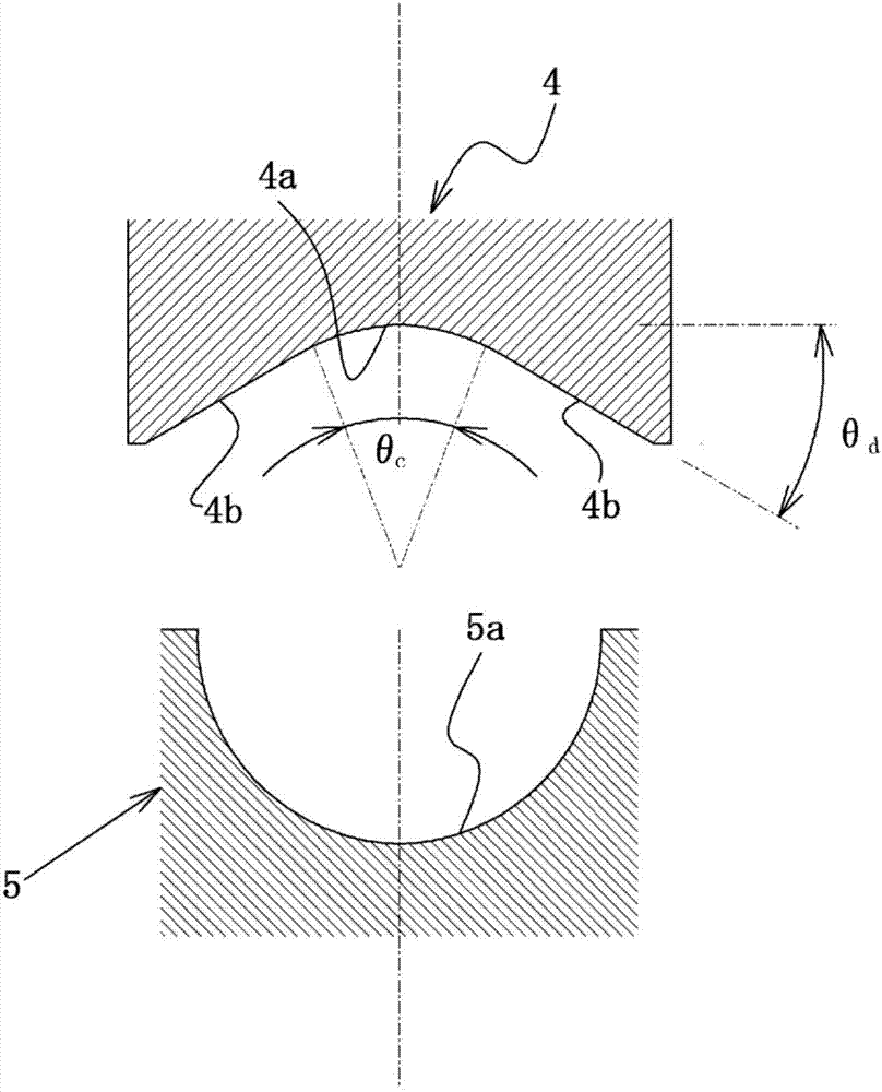
[0120] Next, a lower mold having a concave arc surface with a radius R of 609.6 mm is set on the rod-shaped member, and the molded body having a U-shaped cross-section obtained by bending is pressed from the outside to the apex of the R portion of the mold. The distance between them (the apex of the R portion is the uppermost part of the arc surface in the upper mold, and the lowermost part of the arc surface in the lower mold) becomes 1027 mm, thereby forming an open pipe.

[0...


PUM

PropertyMeasurementUnit
angleaaaaaaaaaa
thicknessaaaaaaaaaa
widthaaaaaaaaaa

Abstract

[Problem] To propose a method for manufacturing steel pipe by implementing a bending process on sheet material, and a press mold used in said method. [Solution] Provided is a method for manufacturing steel pipe that forms a molding (S1), which has a U-shaped cross-section, from a sheet material having an end bent part, forms an open pipe (S2) by applying bending force to the molding, and then butt joins the end surfaces of a gap part of the open pipe (S2) so as to form steel pipe, wherein: at the stage of carrying out the bending process, a lightly worked part to which a much smaller curvature than the other areas is imparted, or an unprocessed part (P), which is not bent, is provided on at least part of the sheet material; and at the stage of pressing down on the molding and forming the open pipe (S2), bending force is applied to sites separated at least W/4 (where W is the width dimension of the sheet material) in the direction of width end parts from the middle of the lightly worked part or unprocessed part (P) without restricting the lightly worked part or the unprocessed part (B). Thus, it is possible to efficiently form steel pipe with a high degree of roundness with comparatively little bending force.

Description

technical field [0001] The present invention relates to a method for manufacturing a steel pipe and a stamping die used in the method. The method is suitable for pressing the formed body into a shape along its length after bending a plate to form a U-shaped shaped body. An open pipe with a gap formed in the side direction (at the ends of the plate width facing each other), and then the end faces of the gap are joined together to form a steel pipe, thereby manufacturing a large-diameter and thick-walled steel pipe for line pipes, etc. . Background technique [0002] As a technology for manufacturing large-diameter and thick-walled steel pipes used for line pipes, etc., the so-called UOE forming technology is widely used, that is, a steel plate with a predetermined length, width, and thickness is stamped into a U-shape, followed by stamping. After the open pipe is formed into an О shape, the gaps are butt-jointed by welding to form a steel pipe, and the diameter is enlarged (...

Claims


Application Information

Patent Timeline
Patent Type & Authority Applications(China)
IPC IPC(8): B21D5/01
CPCB21D5/01B21D5/015
Inventor 堀江正之田村征哉三轮俊博馆野纯一
Owner JFE STEEL CORP
Why Eureka
Try Eureka