Webbing winding device

A technology for a winding device and a seat belt, which is applied to the seat belt in the car, combined with an energy-absorbing device, a belt tensioner, etc.

Inactive Publication Date: 2017-08-01
KK TOKAI RIKA DENKI SEISAKUSHO
View PDF9 Cites 4 Cited by
  • Summary
  • Abstract
  • Description
  • Claims
  • Application Information

AI Technical Summary

Problems solved by technology

[0003] However, in the structure described in Japanese Patent Application Laid-Open No. 2008-1194, if the load input to the seat belt is transmitted to the belt spool through the stopper, the gap formed at the engaging portion of the belt spool and the peripheral portion of the mounting portion Increased stress value

Method used


Image

  • Webbing winding device
  • Webbing winding device
  • Webbing winding device

Examples


Embodiment Construction

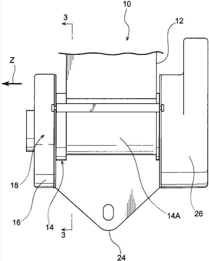
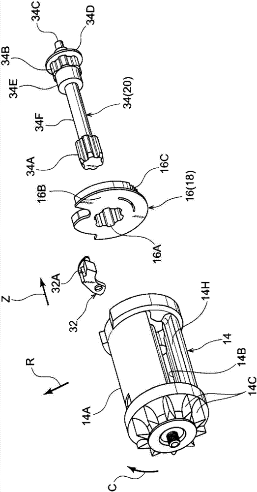
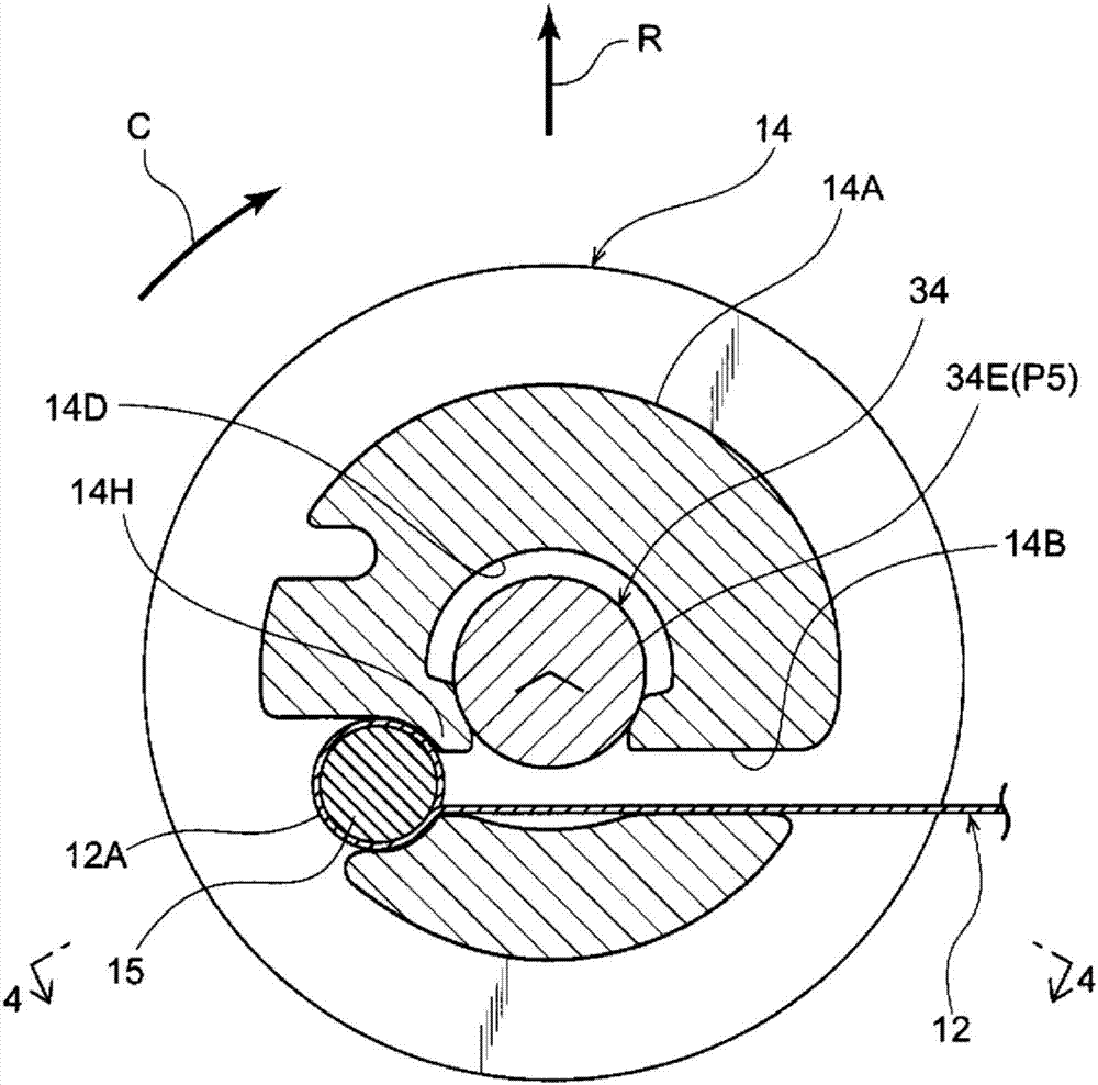
[0016] use Figure 1 ~ Figure 4 The seat belt take-up device according to the embodiment of the present invention will be described. In addition, the arrow Z direction, the arrow R direction, and the arrow C direction appropriately shown in the figure indicate the axial direction, radial direction, and circumferential direction of the tape shaft, respectively. In addition, in the following, when only the axial direction, radial direction, and circumferential direction are shown, unless otherwise specified, the axial direction, radial direction, and circumferential direction of the tape shaft are indicated.

[0017] like figure 1 as well as figure 2 As shown, the seat belt winding device 10 of the present embodiment includes: a belt shaft 14 around which the seat belt 12 to be worn by a passenger is wound, and rotates in the pulling direction when the seat belt 12 is pulled out; and a locking mechanism 18 , which has a locking portion 16 that is configured to be rotatable i...


PUM


Abstract

A webbing winding device (10) is provided with: a spool (14) on which webbing (12) is wound and which has a webbing insertion hole (14B) through which the webbing (12) is passed; and a stopper member (15) which engages with a peripheral edge of the webbing insertion hole (14B) to affix an end of the webbing (12) to the spool (14). The webbing winding device (10) is further provided with load support sections (a portion (P2) which is located on one axial side of a first serration section (34A) and a portion (P5) which is located on the other axial side of a cylindrical section (34E), the first serration section (34A) and the cylindrical section (34E) being formed on a torsion shaft (34)), the load support sections being disposed radially inside the spool (14) relative to the stopper member (15) so as to be located close to the spool (14), the load support sections supporting a load inputted from the webbing (12) to the spool (14) through the stopper member (15).

Description

technical field [0001] The invention relates to a safety belt winding device. Background technique [0002] Japanese Unexamined Patent Publication No. 2008-1194 discloses a seat belt winding device which is provided with a belt shaft (bobbin) which is rotatably supported and around which the seat belt is wound, and a stopper on which one end of the seat belt is fixed. pieces (with plate). According to the spool described in this document, the center portion of the stopper is engaged with the engaging portion formed on the spool, and both end portions (fixed portions) of the stopper are placed on the mounting portion formed on the spool. , thereby fixing the end of the seat belt to the belt shaft. [0003] However, in the structure described in Japanese Patent Application Laid-Open No. 2008-1194, if the load input to the seat belt is transmitted to the belt spool through the stopper, the gap formed at the engaging portion of the belt spool and the peripheral portion of the ...

Claims


Application Information

Patent Timeline
Patent Type & Authority Applications(China)
IPC IPC(8): B60R22/34B60R22/28
CPCB60R22/34B60R2022/287B60R2022/3427B60R22/36
Inventor 福田显司室町哲史
Owner KK TOKAI RIKA DENKI SEISAKUSHO
Why Eureka
Try Eureka