
Devices for filling and/or closing containers with drive shaft purge cartridges

A technology for closing containers and driving shafts, applied in the directions of bottle/container caps, closures, transportation and packaging, etc., can solve the problems of gas outflow, inflow, cap, bottle product pollution, etc., and achieve the effect of good environment

Active Publication Date: 2019-07-16
JBT FOOD & DAIRY SYST BV
View PDF6 Cites 0 Cited by
  • Summary
  • Abstract
  • Description
  • Claims
  • Application Information

AI Technical Summary

Problems solved by technology

[0006] The disadvantage of this structure is that during operation the gas will flow out of the sterilization chamber and into the working area
If organic matter and spores are still present after pre-sterilizing the chamber, or if contamination enters the chamber from the screw-on module, it will flow into the work area and possibly contaminate the lid, bottle and / or product

Method used


Image

  • Devices for filling and/or closing containers with drive shaft purge cartridges
  • Devices for filling and/or closing containers with drive shaft purge cartridges
  • Devices for filling and/or closing containers with drive shaft purge cartridges

Examples


Embodiment Construction

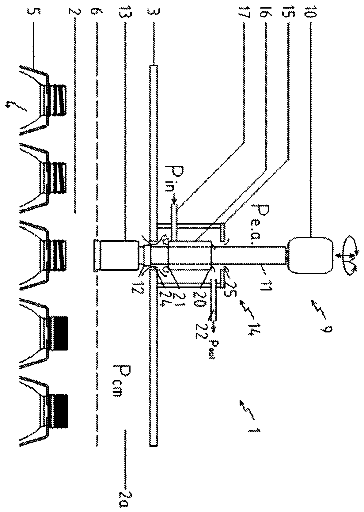
[0030] exist figure 1 , reference numeral 1 denotes the entire device. The device 1 comprises a sterile area 2 which is bounded on its upper side by a ceiling 3 . The bottles 4 are transported with their upper ends through the region 2 by means of bottle holders 5 . During operation, conditioning medium is supplied into the zone 2 by a conditioning medium supply (not shown) connected to the upper part 2 a of the zone 2 . A grid plate 6 is provided to distribute the regulating medium evenly in the entire working area 2 at the upper end of the bottle body 4 .

[0031] On top of the device 1 , in the environment outside the conditioned area 2 , a cap unit 9 is mounted. The unit 9 comprises a servo drive unit 10 enabling the drive shaft 11 to move up and down along the y-axis and also to turn it around the y-axis in order to place and screw on the bottle body 4 a suitable cap, cap, etc. To this end, the drive shaft 11 is provided at its lower end with an operator 12 connectabl...


PUM


Abstract

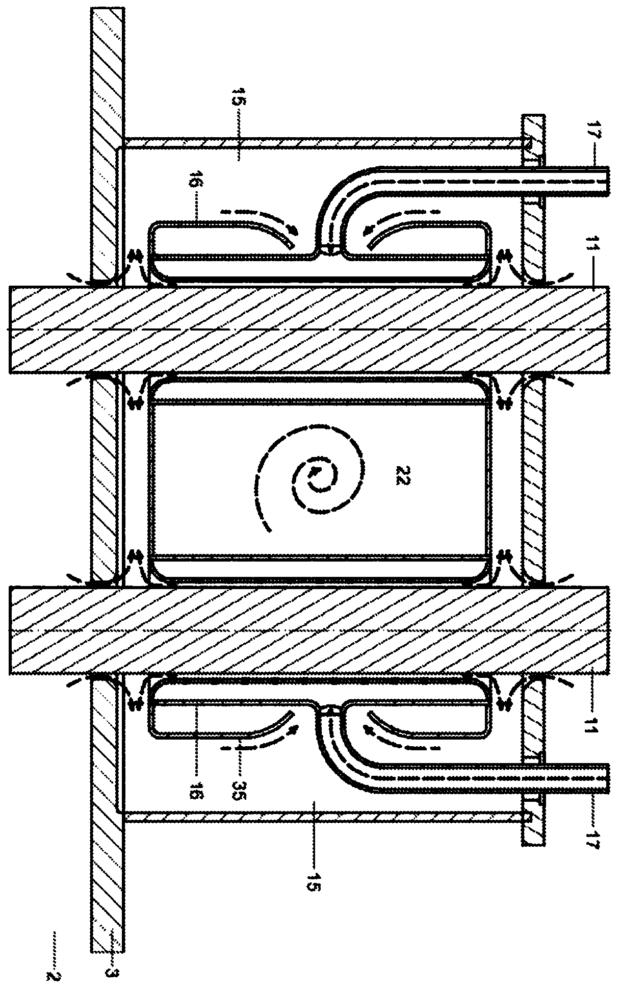
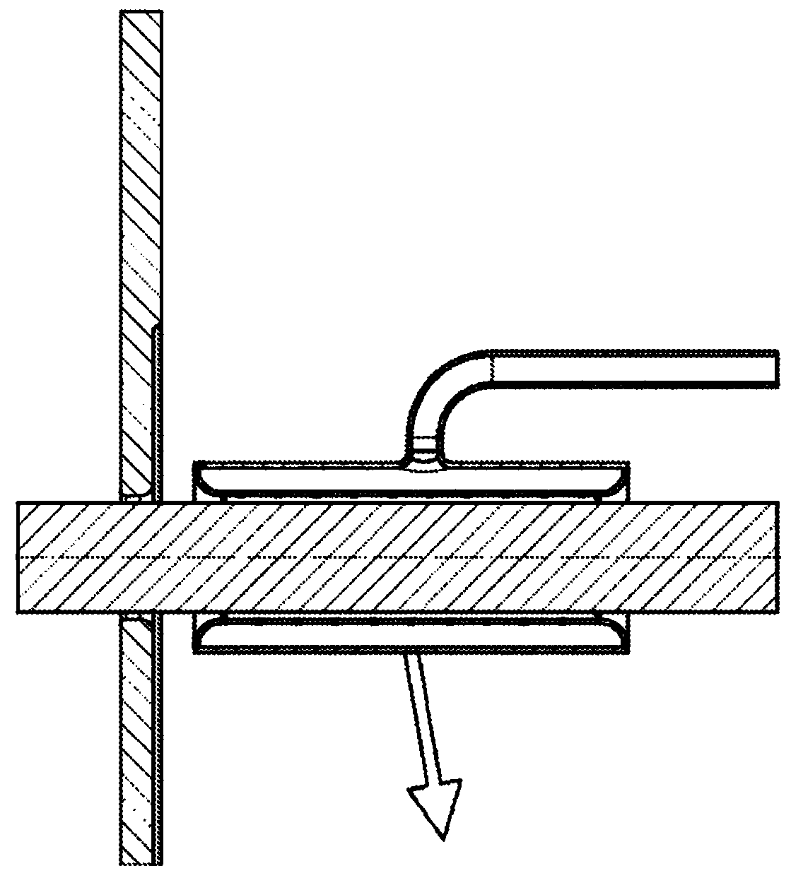
A filling / closing device comprising a regulated area (2) for handling the container. The drive shaft (11) of the operating system can be moved into and out of this regulated area. The drive shaft extends through a clean box (14) equipped with an outer suction chamber (15) and an inner sterilization chamber (16). The sterilization medium supply device (17) is connected with the sterilization chamber, and the discharge device (22) is connected with the suction chamber. One or more outflow gaps (20, 21) are provided connecting the sterilization chamber with the suction chamber. According to the invention, an inner inflow gap ( 24 ) is provided between the suction chamber and the drive shaft, which connects the regulated region to the suction chamber.

Description

technical field [0001] The invention relates to a device for filling and / or closing a container in a conditioned area, especially under sterile or aseptic conditions, the device being equipped with a part enclosing some kind of operating system for carrying out operations on the container Cleaning box for the drive shaft. Background technique [0002] Rotational and translational movements of the capping mechanism are necessary if, for example, it is desired to mount a cap on a container such as a bottle. A part of the drive shaft (also referred to as a turntable) will then continue in and out of the regulated area of ​​the filling and / or closing device. If the device is operated aseptically, the drive shaft will continue into the sterile field. In order to maintain the desired sterile environment, a sterile barrier is required to ensure a hygienic seal between the conditioned area of ​​the closed bottle and especially the outside environment. [0003] For example US 6,49...

Claims


Application Information

Patent Timeline
Patent Type & Authority Patents(China)
IPC IPC(8): B65B55/02B65B7/28B65B55/10B67B3/20
CPCB65B7/2835B65B55/025B65B55/10B67B3/20B67C2003/228B67B2201/08
Inventor B·A·J·克雷克斯
Owner JBT FOOD & DAIRY SYST BV
Learn More