Method for controlling an oil-injected compressor device

A technology of compressors and equipment, applied in the field of speaking, can solve problems such as energy loss

Active Publication Date: 2017-08-01
ATLAS COPCO AIRPOWER NV
View PDF11 Cites 8 Cited by
  • Summary
  • Abstract
  • Description
  • Claims
  • Application Information

AI Technical Summary

Problems solved by technology

[0017] In this case, even when cooling is not required, both the compressor element and the fan for cooling the oil in the cooler continue to be driven by the heat engine at a constant speed if the oil is completely or partially diverted to flow through the bypass, which results in energy loss
[0018] In this known manner, the control of the prevention of condensation is limited to the distribution of the quantity of oil directed through the cooler and the quantity of oil sprayed directly into the compressor element without cooling

Method used


Image

  • Method for controlling an oil-injected compressor device
  • Method for controlling an oil-injected compressor device

Examples


Embodiment Construction

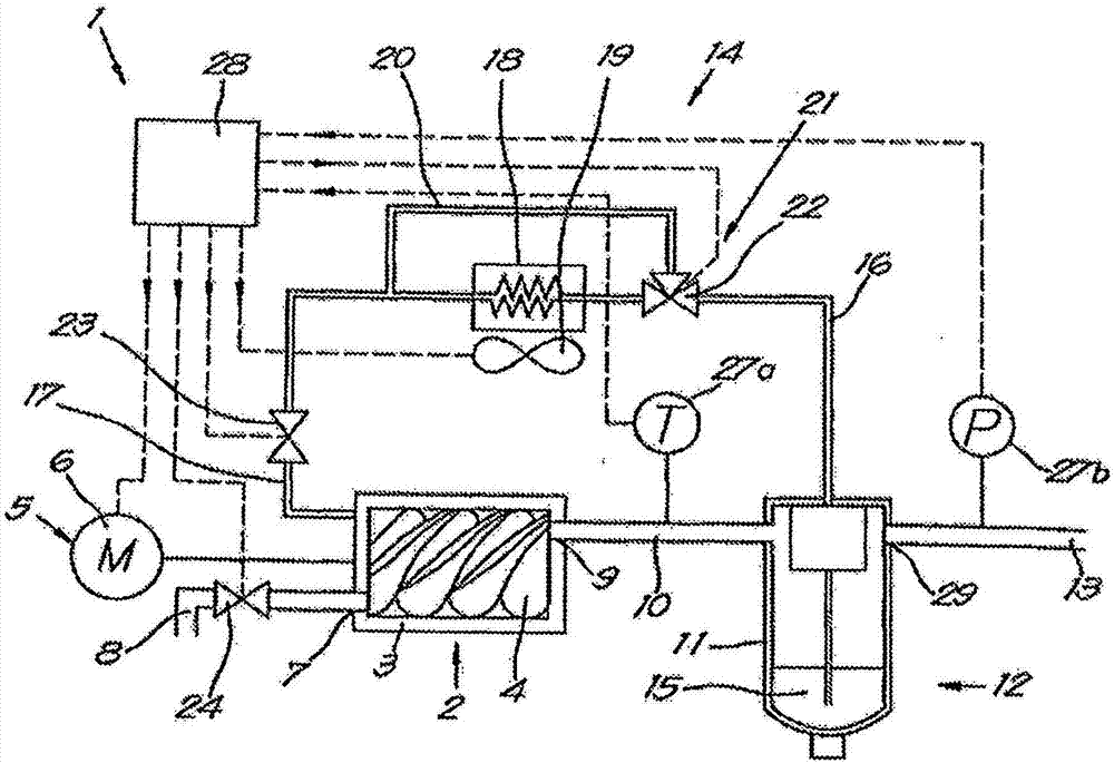
[0039] figure 1 The oil-injected compressor device 1 shown in substantially comprises a compressor element 2, in this case a known screw compressor element, having a housing 3 in which two meshing helical rotors 4 is driven by variable speed controller 5.

[0040] Obviously, the compressor element 2 can also be of a different type, for example a turbo compressor element, without departing from the scope of the present invention.

[0041] In this case, the variable speed controller 5 is a variable speed motor 6 .

[0042] The casing 3 is provided with an air inlet 7 connected to an air inlet pipe 8 for supplying gas to be compressed, eg air, or another gas, or a gas mixture.

[0043] The casing 3 is provided with an exhaust port 9 connected to an exhaust pipe 10 .

[0044] The exhaust pipe 10 is connected via the pressure vessel 11 of the oil separator 12 and the pressure pipe 13 connected thereto to a downstream consumer network for supply to pneumatic tools etc. not shown ...


PUM


Abstract

Method for controlling a compressor device (1) with a compressor element (2) and oil circuit (14) with oil (15) that is injected into the compressor element (2) by a fan (19) via a cooler (18), with a bypass pipe (20) across the cooler (18), whereby when the temperature (T) of the compressor element (2) is less than a value (Tset) the method consists of taking the following steps: the fan (19) is switched off; when the temperature (T) is still less than Tset, the oil (15) is driven via the bypass pipe (20); when the temperature (T) is still less than Tset, the quantity of oil (15) that is injected into the compressor element (2) is decreased until the temperature (T) is equal to Tset.

Description

technical field [0001] The invention relates to a method for controlling an oil-injected compressor installation. [0002] More specifically, the invention applies to oil-injected compressor installations having at least one compressor element with an inlet for the gas to be compressed and an outlet for the compressed gas, Wherein, the compressor device has an oil circuit, and the oil circuit has an oil separator, and the oil separator has an input end connected to the exhaust port of the compressor element and an output end connectable to the compressed gas consumption pipe network, wherein the oil separator Consists of a pressure vessel in which the oil separated from the compressed gas is received and from which the oil can be directed to a cooler which can then be sprayed into the compressor element, wherein the coolant is directed through the cooler by a fan or pump to cool the cooler. Background technique [0003] It is known to vary the speed of the compressor eleme...

Claims


Application Information

Patent Timeline
Patent Type & Authority Applications(China)
IPC IPC(8): F04C29/00F04C29/04
CPCF04C29/0014F04C29/042F04C18/16F04C28/24F04C29/021F04C29/026F04C28/08F04C2270/185F04C2270/195
Inventor W·莫恩斯A·M·J·塞格赫斯
Owner ATLAS COPCO AIRPOWER NV
Why Eureka
Try Eureka