Slide ring seal and method for producing a slide ring seal

A slip ring seal, slip ring technology, applied in the direction of engine seals, engine components, mechanical equipment, etc., can solve the problems of not allowing relative rotation, complex technology, etc., to reduce weight and reduce manufacturing costs.

Inactive Publication Date: 2017-08-01
NETZSCH PUMPEN & SYST
View PDF6 Cites 0 Cited by
  • Summary
  • Abstract
  • Description
  • Claims
  • Application Information

AI Technical Summary

Problems solved by technology

A spring arrangement of this construction is technically complex due to the layering of the sinusoidal springs, since the sinusoidal springs must be aligned exactly with respect to each other and must not be allowed to rotate relative to each other
Furthermore, such a spring arrangement requires many individual parts, which must be mounted accordingly

Method used


Image

  • Slide ring seal and method for producing a slide ring seal
  • Slide ring seal and method for producing a slide ring seal
  • Slide ring seal and method for producing a slide ring seal

Examples


Embodiment Construction

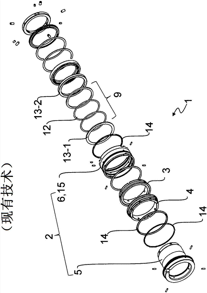
[0028] figure 1An exploded view of the components of a slip ring seal 1 according to the prior art is shown. The slip ring seal 1 has, in particular, a housing part 2 in which a slip ring 4 and a spring-loaded counterpart ring 3 are arranged. The housing assembly 2 comprises a housing element 5 which is designed to move and a housing element 6 which can be fastened in a positionally fixed manner. The movable housing element 5 is also referred to as slip ring seal sleeve, and the stationary fastening housing element 6 is also referred to as slip ring seal housing 15 . In the illustrated embodiment, a movable slip ring 4 is assigned to the movable housing element 5 , while a spring-loaded counterpart ring 3 is assigned to the positionally fixed fastening housing element 6 . In particular, the spring-loaded counterpart ring 3 forms the fixed surface of the slip ring seal 1 , while the slide ring 4 forms the rotatable surface.

[0029] The housing elements 5 , 6 are generally e...


PUM


Abstract

The invention relates to a slide ring seal (1) comprising a housing arrangement (2), a sprung counter ring (3) and a slide ring (4) slidingly associated with the counter ring. The housing arrangement comprises a first movable housing element (5); and a second housing element (6) which can be locked in position. According to the invention, the housing arrangement consists at least partially of a plastic and / or a composite material. The invention further relates to a method for producing a slide ring seal.

Description

technical field [0001] The invention relates to a slip ring seal and a method of producing a slip ring seal according to the features of the preambles of claims 1 and 9 . Background technique [0002] The invention relates to a slip ring sealing device. This is a so-called dynamic seal, which serves to seal the rotatable shaft against a side wall or the like, for example against a housing. The main active parts are two components that can slide one after the other, in particular a spring-loaded slip ring and a corresponding counter ring. One of the two rings is rigidly arranged in the stationary housing element, the other ring is fixed on the rotatable shaft by means of a torsion locking pin or the like. Depending on the type of slip ring seal, the face between the two rings is mostly flat and is usually made of carbon graphite material, metal, ceramic, plastic or carbon compounded with synthetic resin. [0003] US 2006 / 0061041 A1 discloses the construction of a slip ring...

Claims


Application Information

Patent Timeline
Patent Type & Authority Applications(China)
IPC IPC(8): F16J15/34
CPCF16J15/3464F16J15/3452F16J15/3496
Inventor T·施米特F·科奈德A·德恩兹S·魏格尔E·韦伯
Owner NETZSCH PUMPEN & SYST
Why Eureka
Try Eureka