
Laminated body and production method therefor

A manufacturing method and a technology for a laminated body, which are applied in chemical instruments and methods, coatings, layered products, etc., can solve the problems of measurement object error, limited interpretation, and no multiple maxima, and achieve excellent weather resistance. and the effect of adhesion

Active Publication Date: 2019-05-24
SHIN ETSU CHEM IND CO LTD
View PDF11 Cites 0 Cited by
  • Summary
  • Abstract
  • Description
  • Claims
  • Application Information

AI Technical Summary

Problems solved by technology

[0012] On the other hand, when the thin film is a single layer and does not have birefringence (for example, the thin films of Patent Documents 2 and 4), it is considered that there are generally no multiple maximum values, and it is considered that multiple maximum values ​​are found. It is also caused by the vibration of the measurement object and the error of FFT processing
[0013] Therefore, although the power spectrum obtained by Fourier transforming the reflection spectrum of the film has been used in the measurement of film thickness, the physical interpretation related to the splitting of the power spectrum is limited, and the splitting of the power spectrum and the degree of splitting are called stacking. Useful metrics for analyzing the properties of volumes are unknown so far, and such utilization has not yet been made

Method used


Image

  • Laminated body and production method therefor
  • Laminated body and production method therefor
  • Laminated body and production method therefor

Examples


Embodiment

[0214] Synthesis examples, production examples, examples, and comparative examples are shown below to describe the present invention in detail, but the present invention is not limited to the following examples.

[0215] In addition, molecular weight is the number average molecular weight of polystyrene conversion calculated|required by GPC measurement. The viscosity is a value at 25° C. measured using a rotational viscometer.

[0216] (1) Synthesis of compounds

Synthetic example 1

[0217] [Synthesis Example 1] Synthesis of (A)-1

[0218] [chemical 9]

[0219]

[0220]Methyl Silicate 51 (manufactured by Colcoat Co. Ltd., 235 g, 0.5 mol), TBT700 (Nippon Soda ( Co., Ltd., 0.1 g), di-tert-butylhydroxytoluene (0.6 g), and heated to 85°C. Hydroxyethyl acrylate (551 g, 5 mol) was added and reacted there. Distillation of methanol (80 g) was seen. The reaction mixture was heated under reduced pressure (100° C. / 5 mmHg) for 2 hours to obtain (A)-1 as a colorless liquid (95% yield).

Synthetic example 2

[0221] [Synthesis Example 2] Synthesis of (A)-2

[0222] [chemical 10]

[0223]

[0224] Methyl Silicate 51 (manufactured by Colcoat Co. Ltd., 235 g, 0.5 mol), TBT700 (Nippon Soda ( Co., Ltd., 0.1 g), di-tert-butylhydroxytoluene (0.6 g), and heated to 85°C. Hydroxyethyl acrylate (61 g, 0.55 mol) was added and reacted there. Distillation of methanol (15 g) was seen. The reaction mixture was heated under reduced pressure (100° C. / 5 mmHg) for 2 hours to obtain (A)-2 as a colorless liquid (95% yield).


PUM

PropertyMeasurementUnit
thicknessaaaaaaaaaa

Abstract

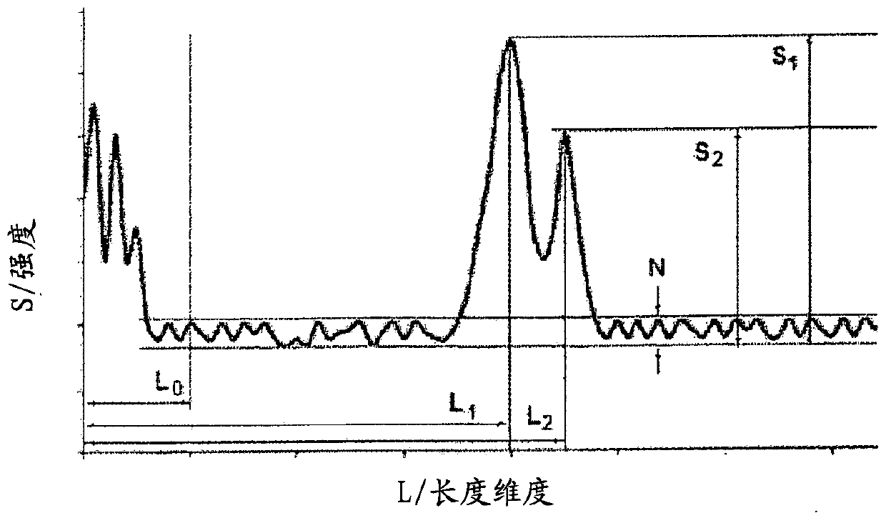
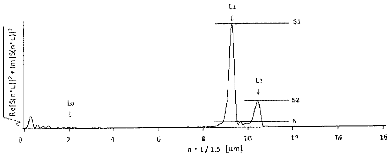
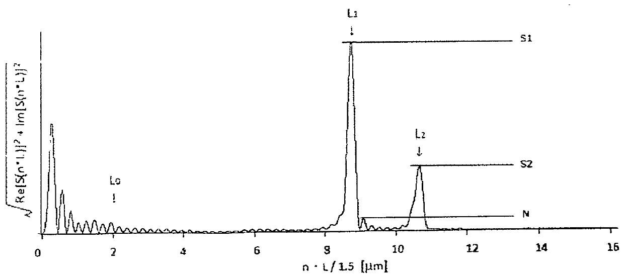
This laminated body comprises an organic resin substrate, and single layer of an active energy ray-curable resin layer (i) and an inorganic deposition layer (ii) that are sequentially laminated on theorganic resin substrate, wherein a power spectrum obtained by performing Fourier transformation on the wavenumber of a reflected wave spectrum obtained by reflectivity spectroscopy at the layer (i) and plotting the amplitude thereof with respect to the length dimension has, at L<1> and L<2> that are equal to or greater than a length dimension threshold L<0>, a first local maximum value S<1> and asecond local maximum value S<2>, respectively, and when L<0> is defined as an arbitrary value within a range of 1-3*10<6> m, in a defined range of the power spectrum excluding the range of L<0> or less, the first local maximum value S<1> has a signal-to-noise ratio S<1> / N of at least 5 with respect to noise N, and the second local maximum value S<2> has a signal-to-noise ratio S<2> / N of at least2 with respect to noise N. The laminated body exhibits, despite the fact that said laminated body has a single intermediate layer composed of an active energy ray-curable film between the organic resin substrate and the inorganic deposition layer, weather fastness and adhesiveness comparable to or better than those of a laminated body having a plurality of thermoset films as intermediate layers.

Description

technical field [0001] The present invention relates to a laminate and a method for producing the same. More specifically, it relates to a laminate in which an active energy ray-curable resin layer and an inorganic vapor-deposited layer are laminated on an organic resin substrate and a method for producing the same. Background technique [0002] The laminate obtained by providing the inorganic vapor-deposited layer on the organic resin substrate has excellent processability and lightness derived from the organic resin, and excellent scratch resistance and chemical resistance derived from the inorganic vapor-deposited layer. Therefore, it has attracted attention as a glass substitute material. [0003] In addition, in such a laminated body, for the purpose of supplementing the weather resistance of the organic resin base material, the purpose of improving the adhesion between the organic resin base material and the inorganic vapor-deposited layer, etc., generally, the organic...

Claims


Application Information

Patent Timeline
Patent Type & Authority Applications(China)
IPC IPC(8): B32B27/00B05D3/06B05D5/06B05D7/24B32B27/16B32B27/36C09D4/02C09D183/02
CPCB05D3/06B05D5/06B32B27/00B32B27/16B32B27/36C09D183/02B05D7/02B05D1/30B05D2451/00B05D2425/01B05D1/62B05D3/0209B05D3/0254B05D2401/10B05D2401/33C08J2369/00B32B7/023B32B27/365B32B27/08C08J7/0423C08J7/08C08J7/16B32B27/283B32B2310/0825B32B2310/0831B32B2310/0887B05D7/24
Inventor 增田幸平
Owner SHIN ETSU CHEM IND CO LTD
Learn More