
Fluid conduit element and method for forming fluid conduit element

A technology for fluid conduits and conduit components, applied in the field of components connecting fluid conduit elements and fluid conduit components, can solve problems affecting the performance of fluid conduits, etc.

Active Publication Date: 2020-07-10
GENERAL ELECTRIC TECH GMBH
View PDF11 Cites 0 Cited by
  • Summary
  • Abstract
  • Description
  • Claims
  • Application Information

AI Technical Summary

Problems solved by technology

As will become apparent, these measures may affect other performance aspects of the fluid conduit

Method used


Image

  • Fluid conduit element and method for forming fluid conduit element
  • Fluid conduit element and method for forming fluid conduit element
  • Fluid conduit element and method for forming fluid conduit element

Examples


Embodiment Construction

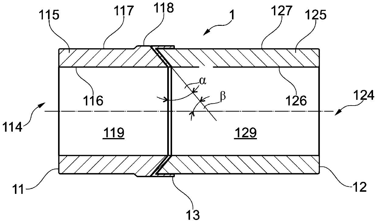
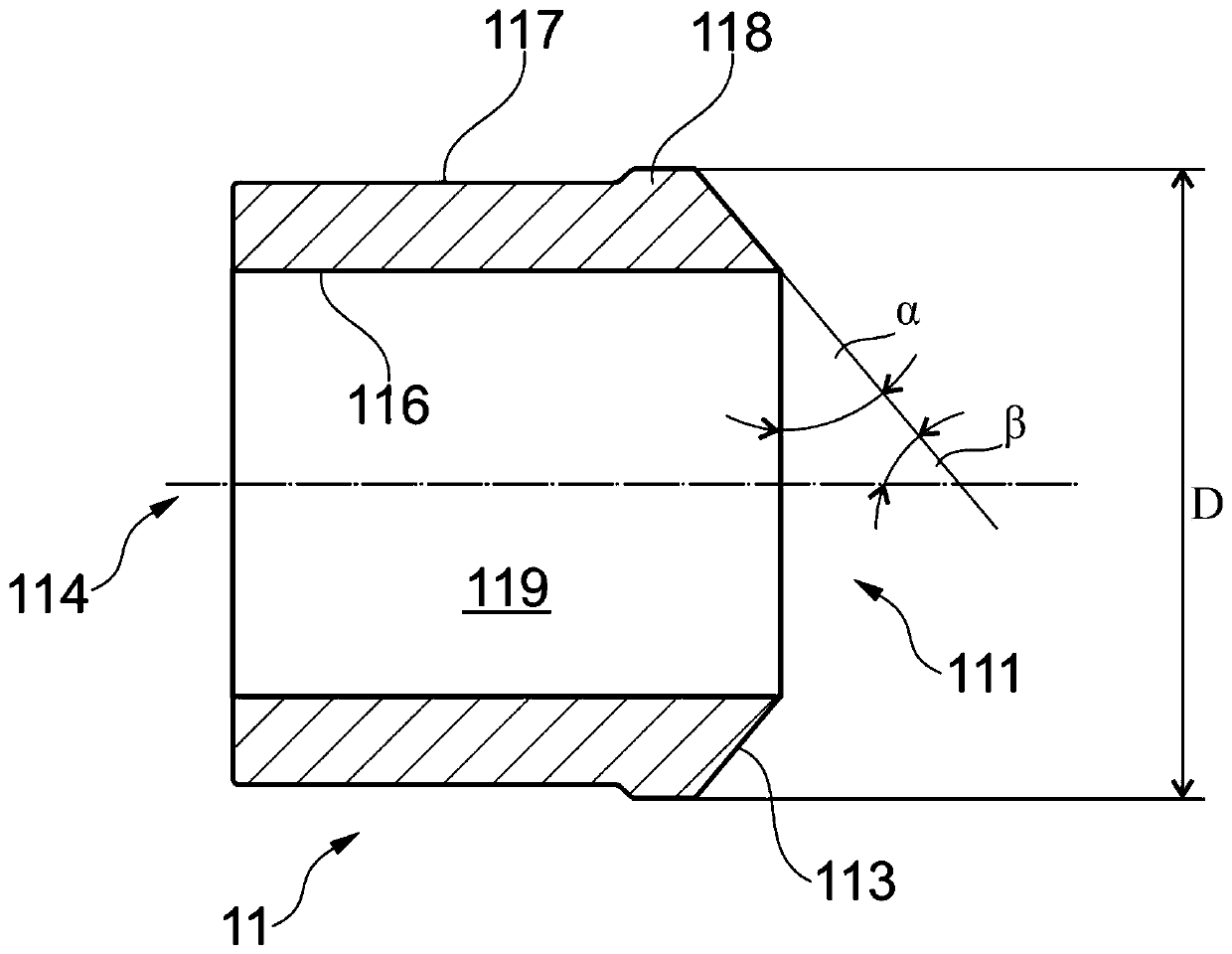
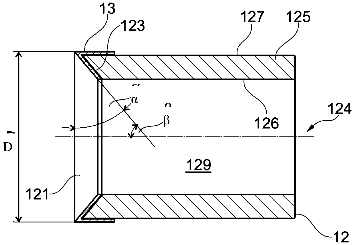
[0040] Exemplary embodiments of the fluid conduit elements or material interface elements disclosed in this specification are further depicted with reference to the accompanying drawings of this summary. Although in this exemplary embodiment the simple fluid conduit member is a tube with circular inner and outer cross-sections for ease of graphical description and understanding, it should be noted that, as noted above, the fluid conduit member may in principle adopt any particular geometry shape. Also the joint surfaces are shown by way of example only and other geometries may be employed within the scope of the claims and without departing from the invention as described and / or claimed herein.

[0041] For a better understanding of the description below, figure 1 A greatly simplified illustration of a fluid conduit member 1 within the scope of the invention is shown. The fluid conduit member basically comprises a first fluid conduit member 11 and a second fluid conduit memb...


PUM


Abstract

Disclosed is a fluid conduit element (1), said fluid conduit element comprising a first fluid conduit member (11) and a second fluid conduit member (12), the fluid conduit members joined to each other, each fluid conduit member comprising a liner (115, 125) and a joint face (111, 121) at which the fluid conduit members are joined to each other, characterized in that the first fluid conduit member joint face (111) is convexly shaped whereby a first fluid conduit member inner wall (116) extends axially further on the joint face than a first fluid conduit member outer wall (117), the second fluid conduit member joint face (121) is concavely shaped whereby a second fluid conduit member outer wall (127) extends axially further on the joint face than a second fluid conduit member inner wall (126), wherein at least one of the first and second fluid conduit members (11, 12) comprises a buttering layer bonded to the respective fluid conduit member liner and arranged at least on one of the respective joint face and the outer wall of the respective fluid conduit member liner in an axial section abutting the respective joint face. Further disclosed is a method for producing a fluid conduit element.

Description

technical field [0001] This disclosure relates generally to the field of fluid conduit systems, and in particular to fluid conduit systems in which, for example, pipe sections composed of different materials are joined. More specifically, the present invention relates to a fluid conduit element as stated in the preamble of claim 1 . Additionally, the present disclosure relates to methods for joining components of a fluid conduit element. Background technique [0002] In fluid conduit systems, eg for conducting fluids in power generation plants, and in process engineering and many other fields, it is often necessary to join conduit sections made of different materials. For example, pipes and other conduits are often made from martensitic or ferritic steels, such as the commonly used ASME SA335 ferritic steel. It may be desirable to join the conduit to conduit sections or to connect it to other types of fluid conduit components made of austenitic steel or nickel-based materi...

Claims


Application Information

Patent Timeline
Patent Type & Authority Patents(China)
IPC IPC(8): F16L13/02
CPCF16L13/02B23K15/0006B23K15/0053B23K26/342B23K2101/06B23K2101/10B23K2103/05
Inventor R.比蒂科菲尔R.拉迪斯M.皮特伦
Owner GENERAL ELECTRIC TECH GMBH
Learn More