
Heat transferring compensating element and electrically operatabla vehicle having such a compensating element

A technology for compensating components and transferring heat, applied in electrical components, heat transfer modification, circuits, etc., can solve problems such as poor thermal conductivity, and achieve effective and reliable heat removal effects

Inactive Publication Date: 2017-08-01
ROBERT BOSCH GMBH
View PDF6 Cites 1 Cited by
  • Summary
  • Abstract
  • Description
  • Claims
  • Application Information

AI Technical Summary

Problems solved by technology

However, the disadvantage of this rubber-like material is its poor thermal conductivity

Method used


Image

  • Heat transferring compensating element and electrically operatabla vehicle having such a compensating element
  • Heat transferring compensating element and electrically operatabla vehicle having such a compensating element
  • Heat transferring compensating element and electrically operatabla vehicle having such a compensating element

Examples


Embodiment Construction

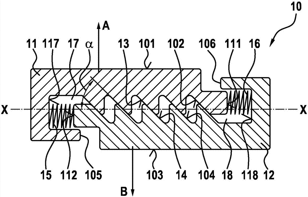
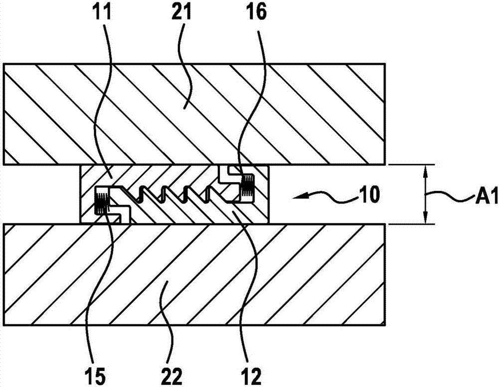
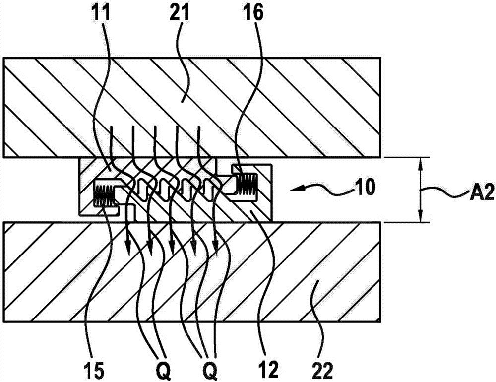
[0025] Refer to the attached Figures 1 to 3 The heat transfer compensating element 10 according to the first embodiment of the present invention will be described in detail.

[0026] The compensation element 10 includes a first heat conducting element 11 and a second heat conducting element 12 . The two heat-conducting elements 11 , 12 are designed identically and can be inserted into one another laterally.

[0027] as by figure 1 It can be seen that the first heat conduction element 11 has a plurality of first inclined planes 13 , and the second heat conduction element 12 has a plurality of second inclined planes 14 . The first heat conducting element 11 has a first contact surface 101 and a second contact surface 102 . Here, the second contact surface 102 includes an inclined plane 13 . In this embodiment a plurality of inclined planes 13 are provided. The second heat conduction element 12 includes a third contact surface 103 and a fourth contact surface 104 .

[0028...


PUM


Abstract

The invention relates to a heat transferring compensating element for heat transfer from a first component to a second component, comprising a first heat conducting element (11) having a first contact surface (101), equipped for contact with the first component, and a second contact surface (102), a second heat conducting element (12) having a third contact surface (103), equipped for contact with the second component, and a fourth contact surface (104), wherein the second contact surface (102) and the fourth contact surface (104) are in direct contact with one another, and wherein between the second and fourth contact surfaces at least one oblique plane (13, 14) is formed, which is at an angle (alpha) to a main axis (X-X) between the first contact surface (101) and the third contact surface (103).

Description

technical field [0001] The invention relates to a compensation element for transferring heat from a first component to a second component and to a vehicle capable of running with muscular and / or motor power, in particular to a compensation element comprising such a heat transfer electric bike. Background technique [0002] There are many areas or components in the prior art which, due to their function, become hotter than their surroundings. Often a controlled conduction of this heat is necessary. To this end, a reliable heat flow from the heat source through the system boundary should be ensured. In principle there are three possibilities for transferring heat, namely convection, heat radiation and heat conduction. Convection is usually not possible in a sealed system. Thermal radiation does not contribute much to heat removal when the temperature difference is small. The most efficient cooling method is usually heat transfer from component to component. Here, the hea...

Claims


Application Information

Patent Timeline
IPC IPC(8): F28F13/00
CPCF28F13/00F28F2013/005F28F2280/08H01M10/613H01M10/625H01M10/6551Y02E60/10
Inventor S·迈尔C·舒马赫V·雅布斯
Owner ROBERT BOSCH GMBH
Learn More