
Combined heat and power plant and method for operation thereof

A cogeneration unit and thermal energy technology, applied in cogeneration systems, heating methods, generators/motors, etc., can solve problems such as unfavorable operation and economy, shutdown of cogeneration units, etc.

Inactive Publication Date: 2014-09-17
SIEMENS AG
View PDF6 Cites 0 Cited by
  • Summary
  • Abstract
  • Description
  • Claims
  • Application Information

AI Technical Summary

Problems solved by technology

Because of the limited storage size, it is possible to shut down the combined heat and power plant after hours of rain or hours of no wind, so there must be additional stored power available in this situation, but this is operationally and economically disadvantageous of

Method used


Image

  • Combined heat and power plant and method for operation thereof

Examples


Embodiment Construction

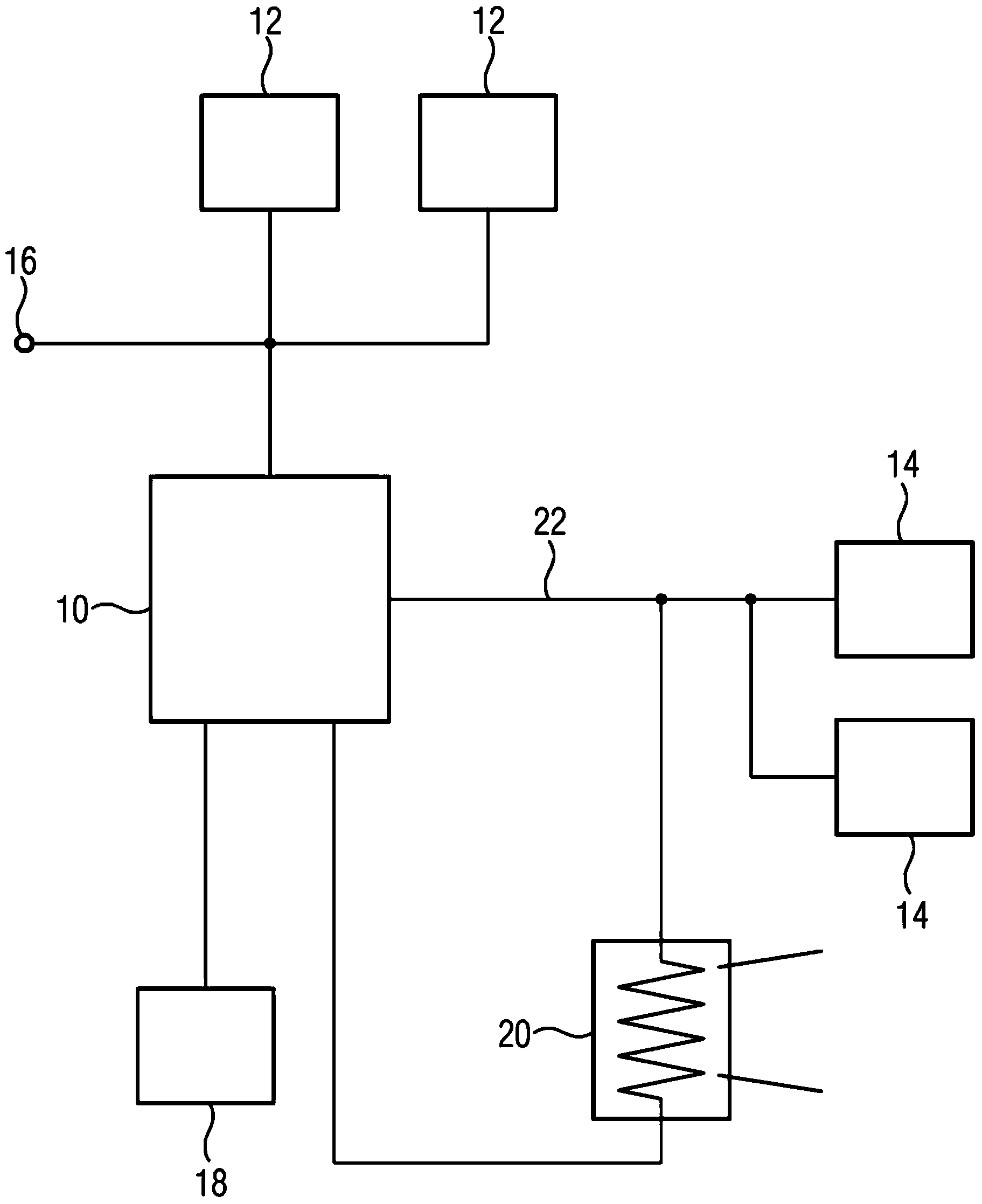
[0016] The combined heat and power unit 10 simultaneously supplies electrical energy to an electrical consumer 12 and thermal energy to a heat consumer 14 and thus has a particularly high efficiency. However, there may also be problems due to the fact that the electrical and thermal power of the combined heat and power unit 10 cannot be adjusted independently of each other. For example, if the electricity consumer 12 or via the connected grid 16 requests high electrical power from the combined heat and power unit 10 , while the heat consumer 14 makes no or only low power demands, then the combined heat and power unit 10 There may be problems with the export of the heat energy generated.

[0017] Part of the excess heat thus generated can be temporarily stored in the accumulator 18 , but if the accumulator 18 becomes overloaded, the combined heat and power unit 10 must be stopped in order to avoid overheating. In particular, load balancing within the grid 16 is urgently requir...


PUM


Abstract

The invention relates to a method for operating a combined heat and power plant (10) for the provision of electrical and thermal energy for at least one load (12, 14), wherein the retrieved heat output is increased when a threshold value for a difference between a provided and retrieved heat output is exceeded.

Description

technical field [0001] The invention relates to a method for operating a cogeneration plant according to the preamble of claim 1 and a cogeneration plant according to the preamble of claim 8 . Background technique [0002] Combined heat and power plants that provide both electrical and thermal energy are becoming increasingly important for energy supply because they firstly have good efficiency and thus low consumption and emission values, and secondly they can be used to balance fluctuations in renewable energy supply. [0003] Cogeneration units are usually operated with heat control or current control, depending on the regulation requirements of the cogeneration unit. In this context, it is known to temporarily store redundantly generated heat in corresponding accumulators when the electrical demand is higher than the thermal demand, thus temporarily decoupling the thermal network from the electrical network. Here, typical storage dimensions allow the CHP to be operated...

Claims


Application Information

Patent Timeline
Patent Type & Authority Applications(China)
IPC IPC(8): F24H9/20F01K23/06F02G5/00H02J3/38F24D18/00
CPCF24H2240/00F01K23/065H02J3/381F02G5/00F24H9/20Y02E20/14F01K13/02Y02P80/15F24D10/003F24D2220/06F24D18/00F24D2101/00F24D2103/13Y02B30/17F02C6/18
Inventor M.考茨M.梅茨格J.谢弗P.沃尔夫拉姆
Owner SIEMENS AG
Learn More