Combined low-voltage switch cabinet and working method thereof

A low-voltage switchgear and combined technology, applied in the field of low-voltage switchgear, can solve the problems that domestic or imported components cannot be arbitrarily selected, the layout of power distribution circuits is not economical and reasonable, and various scheme units cannot be combined, etc., to achieve continuity of operation and High reliability, short power outage time in case of accident, and convenient and safe operation

Inactive Publication Date: 2009-09-02
TIANJIN HAIYANG SWITCHGEAR PLANT
View PDF0 Cites 3 Cited by
  • Summary
  • Abstract
  • Description
  • Claims
  • Application Information

AI Technical Summary

Problems solved by technology

[0002] At present, all kinds of low-voltage switchgears on the market generally have the following shortcomings: First, the cabinet body is too large, the structure is relatively loose, and the series versatility is weak; second, the breaking capacity is low, and the dynamic and thermal stability is relatively low. The third is that the layout of the power distribution circuit is not economical and reasonable enough, and the units of various schemes cannot be combined arbitrarily according to the needs of users; the fourth is that in terms of electrical components, domestic or imported components cannot be arbitrarily selected according to the needs of users

Method used


Image

  • Combined low-voltage switch cabinet and working method thereof
  • Combined low-voltage switch cabinet and working method thereof
  • Combined low-voltage switch cabinet and working method thereof

Examples


Embodiment 1

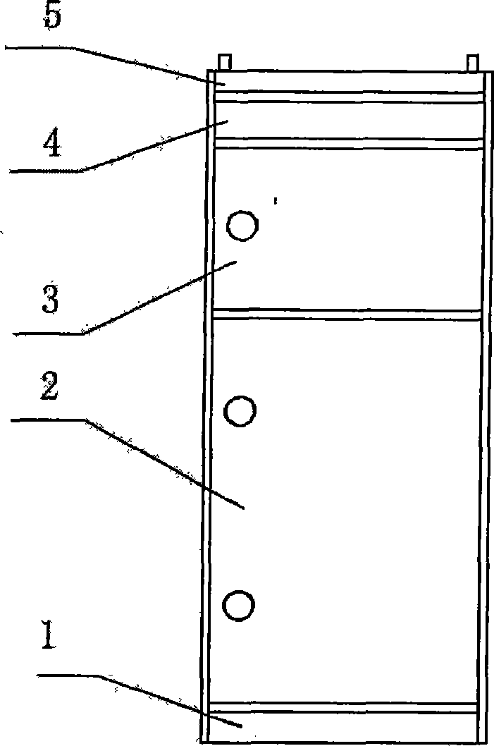
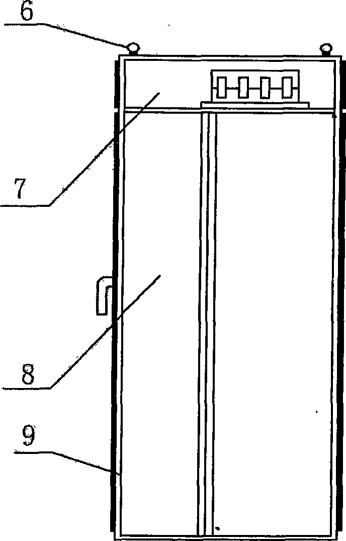
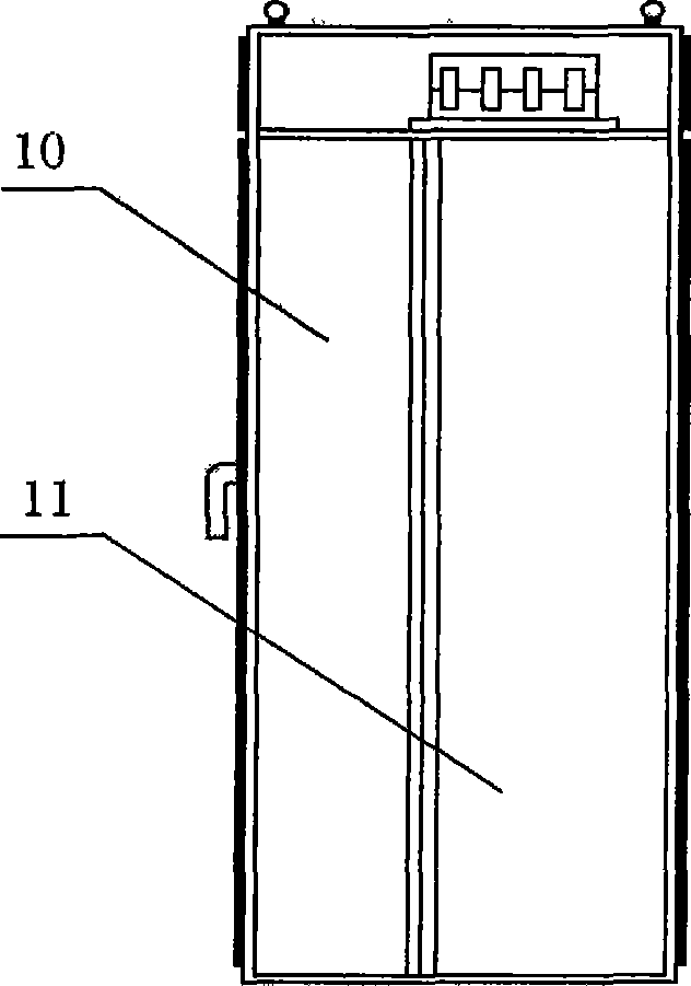
[0023] Embodiment 1: A combined low-voltage switchgear (see attached figure 1 , 2 , 3), it is characterized in that it is made up of switchgear cabinet body, upper ventilation panel 4, lower ventilation panel 1, busbar, instrument, cable and unit room 2 containing functional switching circuit; the top of said switchgear cabinet body There are two hanging rings 6, the uppermost end of the front of the cabinet is eyebrow 5, and the back door 9 is installed on the rear wall of the cabinet; the switch cabinet body is divided into two or more small rooms from top to bottom, and the uppermost small room is the upper busbar room 7, The small room on the second floor from top to bottom is the instrument room 3, and the lower floors are each functional unit room 2; each functional unit room 2 is connected to the vertical bus bar 11; the rear end of the functional unit room 2 of the cabinet has a storage for cables The cable room 10; the upper ventilation plate 4 is installed on the fr...

Embodiment 2

[0032] Embodiment 2: A combined low-voltage switchgear (see attached figure 1 , 2 , 3), it is characterized in that it is made up of switchgear cabinet body, upper ventilation panel 4, lower ventilation panel 1, busbar, instrument, cable and unit room 2 containing functional switching circuit; the top of said switchgear cabinet body There are two hanging rings 6, the uppermost end of the front of the cabinet is eyebrow 5, and the back door 9 is installed on the rear wall of the cabinet; the switch cabinet body is divided into two or more small rooms from top to bottom, and the uppermost small room is the upper busbar room 7, The small room on the second floor from top to bottom is the instrument room 3, and the lower floors are each functional unit room 2; each functional unit room 2 is connected to the vertical bus bar 11; the rear end of the functional unit room 2 of the cabinet has a storage for cables The cable room 10; the upper ventilation plate 4 is installed on the fr...


PUM


Abstract

The invention relates to a combined low-voltage switch cabinet and a working method thereof. The combined low-voltage switch cabinet is characterized by consisting of a cabinet body of the switch cabinet, an upper ventilation plate, a lower ventilation plate, a bus, an instrument, a cable and a unit room with a functional switch circuit. The working method comprises the steps of: 1) the installation of the cabinet body, 2) the selection of a circuit proposal, 3) the internal connection of the switch cabinet, 4) the external connection of the switch cabinet, 5) the running of the switch cabinet and 6) the operation of a user. The invention has the advantages of compact structure, ability of saving the volume of the cabinet body, strong seriation and universality, high breaking ability, good dynamic thermal stability, advanced and reasonable structure, economic layout of a power distribution circuit and arbitrary combination of various proposals and units; a functional unit adopts a fixed structure, thereby facilitating the safe running, facilitating the overhaul, shortening the accident power outage time and ensuring the reliable power use; an electrical appliance element can select a domestic element or an imported element arbitrarily according to the different user demands, thereby being capable of meeting the market demands to the maximum extent; furthermore, the combined low-voltage switch cabinet has beautiful appearance, high protection level, high operation continuity and reliability and convenient installation and maintenance.

Description

(1) Technical field: [0001] The invention belongs to a low-voltage switchgear, in particular to a combined low-voltage switchgear and its working method. (two) background technology: [0002] At present, all kinds of low-voltage switchgears on the market generally have the following shortcomings: First, the cabinet body is too large, the structure is relatively loose, and the series versatility is weak; second, the breaking capacity is low, and the dynamic and thermal stability is relatively low. The third is that the layout of the power distribution circuit is not economical and reasonable enough, and the units of various schemes cannot be combined arbitrarily according to the needs of users; the fourth is that in terms of electrical components, domestic or imported components cannot be arbitrarily selected according to the needs of users. (3) Contents of the invention: [0003] The purpose of the present invention is to address the above problems, to provide a combined l...

Claims


Application Information

Patent Timeline
Patent Type & Authority Applications(China)
IPC IPC(8): H02B1/30H02B1/56H02B1/26H02B1/50H02B1/24H02J3/00H02P1/00
Inventor 肖永红齐则利高宇金
Owner TIANJIN HAIYANG SWITCHGEAR PLANT
Why Eureka
Try Eureka