Display device fitted with position input function
A display device and functional technology, applied in the input/output process of data processing, static indicators, optics, etc., can solve the problems of reduced sensitivity of position detection, susceptibility to interference, low degree of freedom of touch detection time, etc., to provide position The effect of detection sensitivity
- Summary
- Abstract
- Description
- Claims
- Application Information
AI Technical Summary
Problems solved by technology
Method used
Image

Examples
no. 1 approach
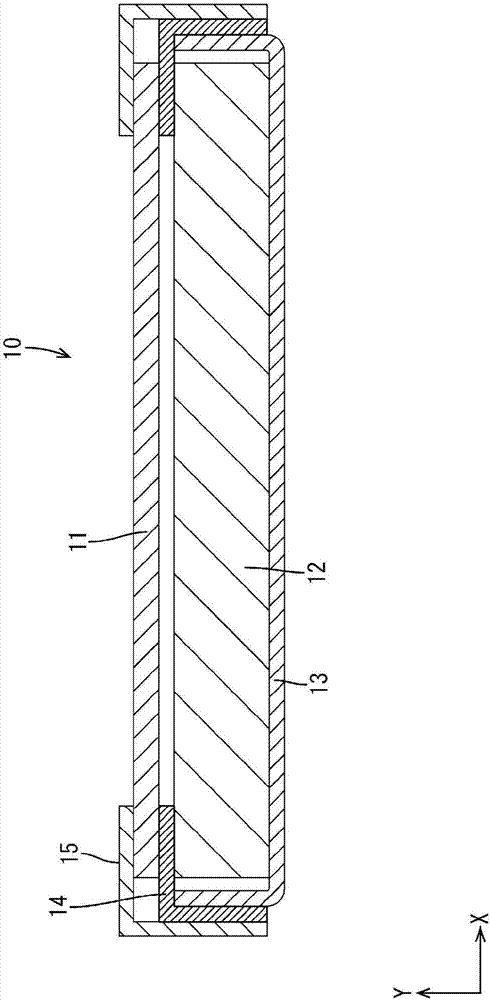
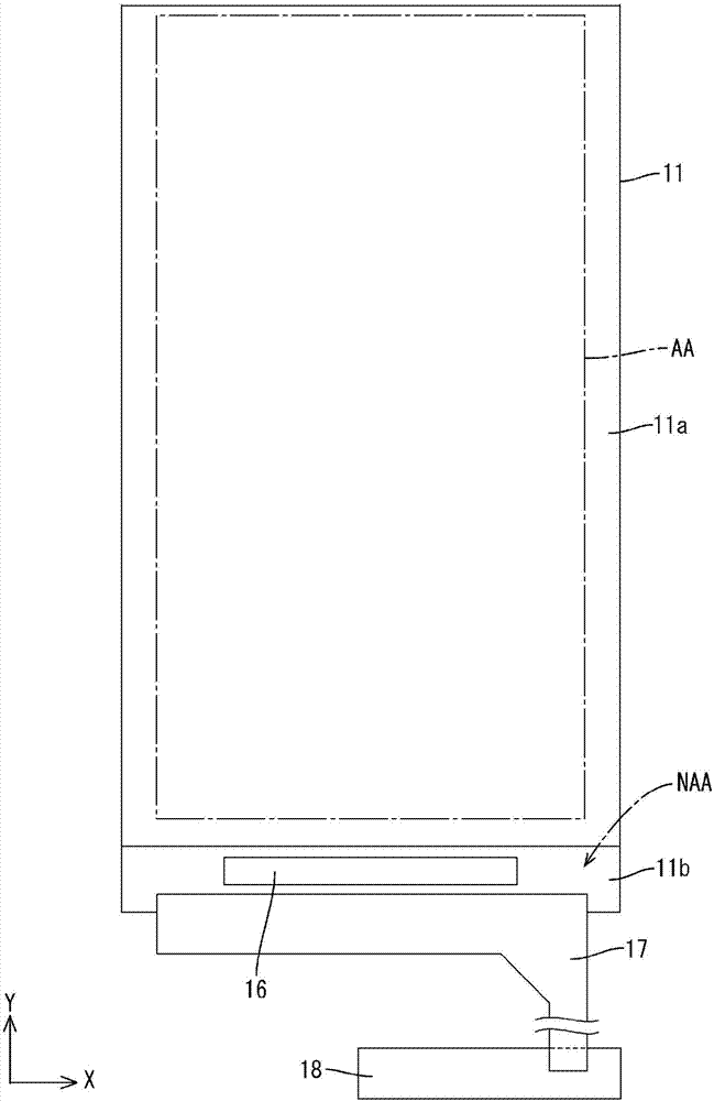
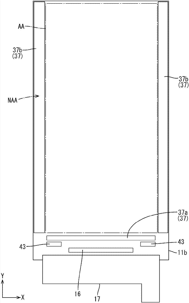
[0043] according to Figure 1 to Figure 14 The first embodiment of the present invention will be described. In this embodiment, a liquid crystal display device having a position input function (display device having a position input function) 10 will be described as an example. In addition, X-axis, Y-axis, and Z-axis are shown in the partial drawings, and the directions of the respective axes are drawn to coincide with the directions shown in the respective drawings. In addition, regarding the up and down direction is figure 2 etc., and the upper side in the figure is taken as the surface, and the lower side in the figure is taken as the reverse side.
[0044] Such as figure 1 and figure 2 As shown, the liquid crystal display device 10 has: a liquid crystal panel (display panel with a position input function) 11, the liquid crystal panel shown displays an image, and based on the displayed image, the position information input by the user can be detected; a backlight devi...
no. 2 approach
[0086] according to Figure 15 A second embodiment of the present invention will be described. In this second embodiment, the time of the position detection period is changed. In addition, the description of the same structure, operation, and effect as those of the above-mentioned first embodiment will not be repeated.
[0087] like Figure 15 As shown, the main control unit according to the present embodiment controls the touch controller so that the drive electrode is driven by supplying the drive signal Vdri across the scan writing period and the stop period included in the display period, and detects During the stop period, the position detection signal Vdet output by the detection electrode is detected. That is, the position detection period (time pt5 to time pt6, time pt7 to time pt8) is performed so as to straddle the scan writing period and the stop period. During the stop period included in the display period, since the TFT drive is stopped, noise is less likely t...
no. 3 approach
[0091] according to Figure 16 A third embodiment of the present invention will be described. In this third embodiment, the number of position detection periods corresponding to one scan writing period in the first embodiment is changed. In addition, the description of the same structure, operation, and effect as those of the above-mentioned first embodiment will not be repeated.
[0092] like Figure 16 As shown, the main control unit according to this embodiment controls the touch controller so that the drive electrodes are driven by supplying the drive signal Vdri to the drive electrodes twice in the scan writing period included in the display period. That is, the position detection periods (time pt9 to time pt10, time pt11 to time pt12, time pt13 to time pt14, time pt115 to time pt16) are included twice in each scanning write period. Thereby, the position detection result can be statistically analyzed, and the deterioration of the position detection sensitivity due to t...
PUM
| Property | Measurement | Unit |
|---|---|---|
| Electron mobility | aaaaa | aaaaa |
Abstract
Description
Claims
Application Information
 - R&D
- Intellectual Property
- Life Sciences
- Materials
- Tech Scout
- Unparalleled Data Quality
- Higher Quality Content
- 60% Fewer Hallucinations
Browse by: Latest US Patents, China's latest patents, Technical Efficacy Thesaurus, Application Domain, Technology Topic, Popular Technical Reports.
© 2025 PatSnap. All rights reserved.Legal|Privacy policy|Modern Slavery Act Transparency Statement|Sitemap|About US| Contact US: help@patsnap.com