
Rectifier having high voltage class

A rectifier and high-voltage technology, applied in the field of rectifiers, can solve the problems of low material utilization, low voltage stabilization accuracy, and increased manufacturing costs, and achieve the effects of avoiding magnetization, stable working conditions, and reducing energy consumption.

Inactive Publication Date: 2019-08-09
HARBIN UNIV OF SCI & TECH
View PDF8 Cites 2 Cited by
  • Summary
  • Abstract
  • Description
  • Claims
  • Application Information

AI Technical Summary

Problems solved by technology

[0002] With the development of electronic technology, rectifiers are widely used in various industries, and all aspects of power transmission will be involved. According to the voltage requirements of different products, rectifiers of corresponding specifications are selected. Among them, in the prior art, high voltage applications to All the rectifiers in this field have the following defects, 1: the heat dissipation effect inside the rectifier is poor, resulting in poor actual rectification work effect; 2: the silicon rectifier DC voltage regulator used in the prior art has low voltage stabilization accuracy in the actual work process, and the manufacturing process High copper consumption increases production cost; 3: The rectifiers in the prior art cannot be used in multiple groups; 4: The high-voltage rectifiers in the prior art consume large power and poor optimization. The rectifier transformer wiring method has low utilization rate of materials

Method used


Image

  • Rectifier having high voltage class
  • Rectifier having high voltage class
  • Rectifier having high voltage class

Examples


Embodiment

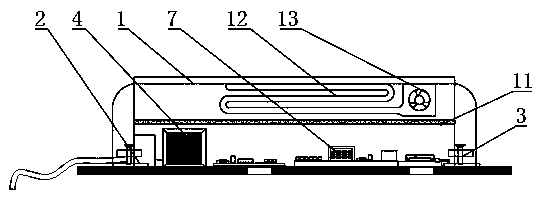
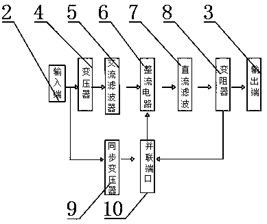
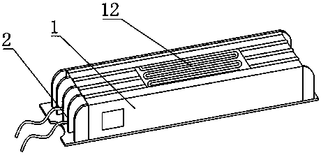
[0029] like Figure 1-6 As shown, the present invention provides a high-voltage level rectifier, including a device body 1, the two ends of the device body 1 are respectively provided with an input end 2 and an output end 3, and the inner bottom side of the device body 1 is close to the input end 2. A transformer 4 is installed on one side, an AC filter 5 is provided on one side of the transformer 4, a rectification circuit 6 is provided on one side of the AC filter 5, and a DC filter 7 is provided on one side of the rectification circuit 6. , one side of the DC filter 7 is provided with a rheostat 8, one end of the input terminal 2 in the internal circuit of the device main body 1 is connected to the synchronous transformer 9, and the other end of the rheostat 8 is connected to the rectifier circuit 6 through a parallel port 10 , an interlayer 11 is added at the inner middle position of the main body 1 of the device, and a water-cooled pipe 12 is arranged on the upper side of...


PUM


Abstract

The invention provides a rectifier having a high voltage class. The rectifier comprises a device body, wherein two ends of the device body are provided with an input end and an output end respectively; the inner bottom side end of the device body is provided with a transformer at a side close to the input end; one side of the transformer is provided with an AC filter; one side of the AC filter isprovided with a rectifier circuit; one side of the rectifier circuit is provided with a DC filter; one side of the DC filter is provided with a rheostat; one end of the input end of the internal circuit of the device body is connected with a synchronous transformer; the interior of the AC filter is composed of a capacitor and a transformer; and a thyristor is disposed in the DC filter. By means ofa spiral water-cooling pipeline, in actual operation, water circulation cooling can reduce the temperature inside the rectifier, prevents the over-high internal temperature from affecting the actualoperation process. Further, compared with the mode of a traditional rectifier having a high voltage class, the water cooling mode is less likely to produce noise and achieves a stable working condition.

Description

technical field [0001] The invention relates to the technical field of rectifiers, in particular to a high-voltage rectifier. Background technique [0002] With the development of electronic technology, rectifiers are widely used in various industries, and all aspects of power transmission will be involved. According to the voltage requirements of different products, rectifiers of corresponding specifications are selected. Among them, in the prior art, high voltage applications to All the rectifiers in this field have the following defects, 1: the heat dissipation effect inside the rectifier is poor, resulting in poor actual rectification work effect; 2: the silicon rectifier DC voltage regulator used in the prior art has low voltage stabilization accuracy in the actual working process, and the manufacturing process 3: The rectifiers in the prior art cannot be used in multiple groups; 4: The high-voltage rectifiers in the prior art consume large power and poor optimization. ...

Claims


Application Information

Patent Timeline
Patent Type & Authority Applications(China)
IPC IPC(8): H02M7/17H02M1/12H02M1/14H05K7/20
CPCH02M1/126H02M1/14H02M7/17H05K7/20927
Inventor 周封卢松恒谭晓东任冬冬赵昱翔
Owner HARBIN UNIV OF SCI & TECH
Learn More