Control apparatus determining transformer magnetization in a DC/DC converter based on difference between primary and secondary currents

a technology of transformer magnetization and control apparatus, which is applied in the direction of dc-dc conversion, power conversion systems, instruments, etc., can solve the problems of low accuracy of magnetization bias prediction, inability to accurately correct and inability to prevent offset errors, so as to reduce the magnetization bias of the transformer and appropriately reduce the effect of offset error

Active Publication Date: 2019-03-05
SOKEN CO LTD +1
View PDF4 Cites 5 Cited by
  • Summary
  • Abstract
  • Description
  • Claims
  • Application Information

AI Technical Summary

Benefits of technology

[0008]The present disclosure is achieved in light of the above-described circumstances and provides a control apparatus capable of appropriately suppressing the magnetization bias by accurately predicting an amount of magnetization bias of the transformer.
[0011]In the case where a magnetization bias has occurred on the transformer, current flowing through the rectifier circuit during a period in which each of the first input switch and the second input switch turn ON is varied because of an influence of the magnetization bias. Also, an offset error which is a DC (direct current) component superposed on the detection value of the current sensor is constant regardless of the offset error. Hence, according to the present application, the first current is acquired as the detection value of the current sensor during an ON period where the first input switch turns ON, and the second current is acquired as the detection value of the current sensor during an ON period where the second input switch turns ON. Then, an amount of the magnetization bias of the transformer is predicted based on the difference between the first current and the second current, whereby the offset error is prevented from affecting the prediction of the magnetization bias. Subsequently, in accordance with the predicted magnetization bias, a reduction process changes the drive mode of the inverter circuit or the rectifier circuit, in order to reduce the magnetization bias of the transformer. Thus, an amount of magnetization bias can be predicted accurately and the magnetization bias can be appropriately reduced.

Problems solved by technology

In the case where an amount of the magnetization bias is predicted by using the current detection device as disclosed in the above-described patent literature, the current detected by the current detection device may include offset errors.
Hence, the offset error may lower the accuracy of the prediction of the magnetization bias.
When the prediction accuracy of the magnetization bias is lowered, the magnetization bias of the transformer is unlikely to be corrected appropriately.

Method used


Image

  • Control apparatus determining transformer magnetization in a DC/DC converter based on difference between primary and secondary currents
  • Control apparatus determining transformer magnetization in a DC/DC converter based on difference between primary and secondary currents
  • Control apparatus determining transformer magnetization in a DC/DC converter based on difference between primary and secondary currents

Examples


first embodiment

[0030](First Embodiment)

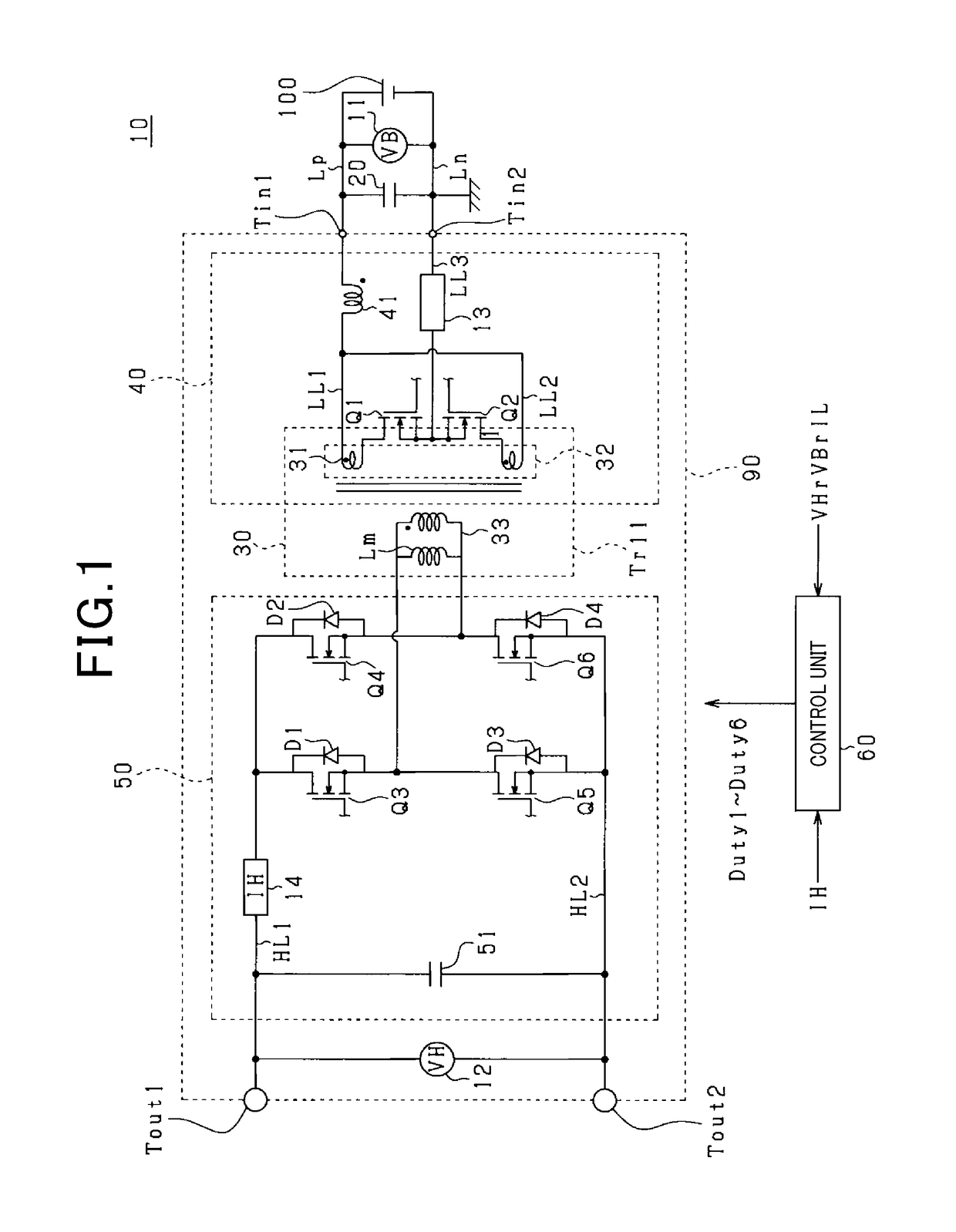
[0031]FIG. 1 is a configuration of a power conversion system 10 according to a first embodiment. The power conversion system 10 boosts DC voltage supplied from a storage battery 100, and supplies power based on the boosted DC voltage to equipment as an object to be supplied with the power, which is electrically connected to a first output terminal Tout1 and a second output terminal Tout2. The equipment includes other on-board equipment, and power storage devices other than the storage battery 100, for example.

[0032]The power conversion system 10 includes a filter capacitor 20 and a DC-DC converter 90. The filter capacitor 20 is connected in parallel between the positive terminal and the negative terminal of the storage battery 100.

[0033]The DC-DC converter 90 includes a first circuit 40, a transformer 30 and a second circuit 50. The first circuit 40 is a current type converter that converts DC current to AC current (i.e., the first circuit 40 is an inverter c...

second embodiment

[0102](Second Embodiment)

[0103]According to the second embodiment, configurations different from that of the first embodiment will mainly be described.

[0104]According to the second embodiment, the control unit 60 performs a peak current mode control in which OFF timings of the first and second switches Q1 and Q2 are set based on the peak value of the primary side current IL flowing through the first circuit 40.

[0105]FIG. 8 is a functional block diagram illustrating a function of a peak current mode control in functions of the control unit 60. In FIG. 8, the primary side setting unit 65 is provided with a first peak current mode control unit 67 that sets the first drive command value Dcc1 of the first switch Q1, and a second peak current mode control unit 68 that sets the second drive command value Dcc2 of the second switch Q2.

[0106]The first peak current mode control unit 67 is provided with a DA converter 341, a comparator 342, an adder 343, a RS flipflop 347, and a Duty limiting u...

third embodiment

[0125](Third Embodiment)

[0126]According to the third embodiment, configurations different from that of the first embodiment will mainly be described.

[0127]According to the third embodiment, ON periods of the third to sixth switches Q3 to Q6 of the second circuit 50 are change, whereby the ET product is adjusted and the magnetization bias is reduced.

[0128]In the A mode, when the third and sixth switches Q3 and Q6 are OFF, the secondary winding voltage Vt produced on the third coil 33 is calculated in accordance with the following equation (6).

Vt(Aoff)=VHr+Vf1+Vf4  (6)

Vt (Aoff) is secondary winding voltage Vt when both of the third switch Q3 and the sixth switch Q6 are OFF. Vf1 and Vf4 are forward direction voltage of the first and fourth reflux diodes D1 and D4 respectively.

[0129]In the A mode, the secondary winding voltage Vt when both of the third and sixth switches Q3 and Q6 are ON is calculated in accordance with the following equation (7).

Vt(Aon)=VHr+Vrom3+Vrom6  (7)

Vt (Aon) is ...


PUM


Abstract

A control unit capable of accurately calculating a magnetization bias of a transformer is provided, thereby appropriately reducing the magnetization bias. The control unit acquires first and second currents that flow through a transformer during a period where either first or second switches individually turn ON. The control unit predicts an amount of magnetization bias in either positive side or negative side of the excitation current that flows through the transformer. The control unit reduces the magnetization bias of the transformer based on the predicted amount of magnetization bias.

Description

CROSS-REFERENCE TO RELATED APPLICATION[0001]This application is based on and claims the benefit of priority from earlier Japanese Patent Application No. 2017-102885 filed May 24, 2017, the description of which is incorporated herein by reference.BACKGROUND[0002]Technical Field[0003]The present disclosure relates to a control apparatus that suppresses the magnetization bias of a transformer.[0004]Description of the Related Art[0005]Conventionally, a power conversion apparatus in which a primary circuit and a secondary circuit are connected through a transformer is known. According to the above-mentioned power conversion apparatus, magnetization bias may occur on the transformer in which magnetic flux is biased. The magnetization bias of the transformer can be predicted using an amount of deviation in the excitation current which produces the magnetic flux in the transformer.[0006]In this respect, Japanese Patent Application Laid-Open Publication Number 2016-192889 discloses a power c...

Claims


Application Information

Patent Timeline
Patent Type & Authority Patents(United States)
IPC IPC(8): H02M3/335H02M1/00
CPCH02M3/33576H02M2001/0009H02M3/33507H02M1/0009
Inventor IYASU, SEIJIHAYASHI, YUJIHANDA, YUICHI
Owner SOKEN CO LTD
Why Eureka
Try Eureka