Magnetic recording device

a recording device and magnetic technology, applied in the field of magnetic recording devices, can solve the problem that the assisting effect of the microwave cannot be used to the greatest extent possibl

Active Publication Date: 2014-03-11
HITACHI LTD
View PDF6 Cites 7 Cited by
  • Summary
  • Abstract
  • Description
  • Claims
  • Application Information

AI Technical Summary

Benefits of technology

[0013]To effectively exhibit assisting effects caused by a microwave magnetic field generated from a spin-torque oscillator in a microwave assisted recording method, it is important that a frequency of the microwave magnetic field corresponds to a magnetic resonance frequency of a recording medium. It is because, in the microwave assisted recording method, a coercive force of magnetization of a medium is considerably reduced by ferromagnetic resonance of the microwave magnetic field and the magnetization of the medium, and consequently, a magnetization inversion magnetic field of the recording medium is considerably reduced.
[0015]A microwave magnetic field frequency is known to correlate with intensity of a magnetic field applied on the spin-torque oscillator. As the intensity of the magnetic field is increased, the microwave magnetic field frequency is increased. Spin-torque oscillation is generated by counterbalance of spin-torque received by an FGL due to the spin of the spin-torque oscillator and an external magnetic field. When the spin-torque oscillator receives a strong magnetic field from the outside, the relaxation time of magnetization of the FGL is shortened and the magnetization rotation speed is increased. At the same time, the oscillation frequency of FGL magnetization is increased, i.e., the frequency of the microwave magnetic field is increased.

Problems solved by technology

Accordingly, the assisting effects of the microwave cannot be used to the greatest extent possible.

Method used


Image

  • Magnetic recording device
  • Magnetic recording device
  • Magnetic recording device

Examples


first embodiment

[ Summary]

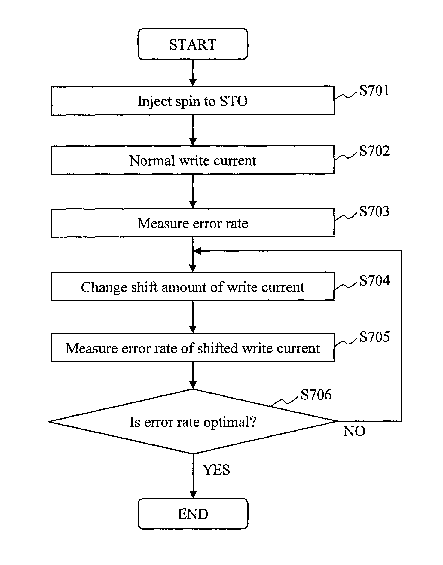
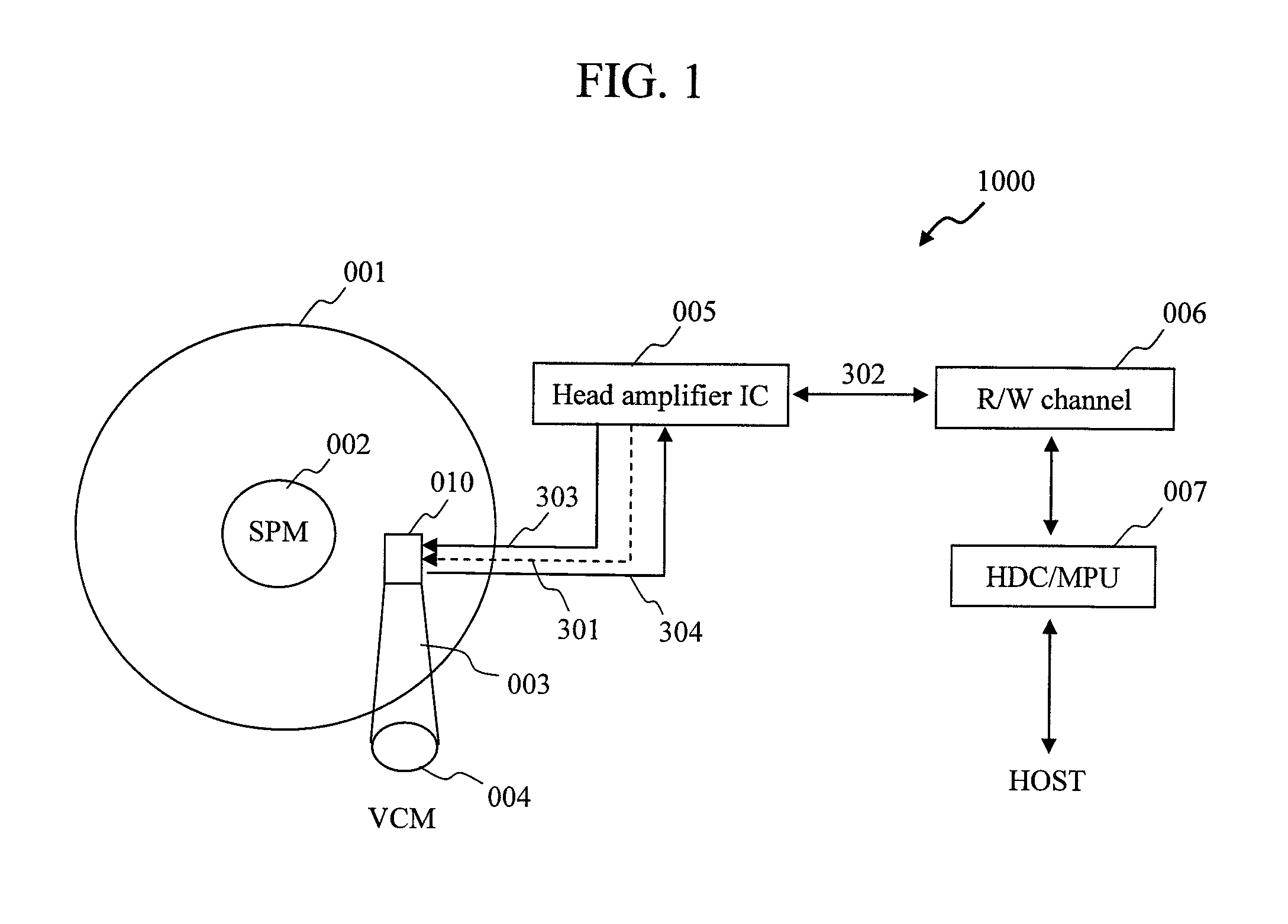
[0079]The magnetic recording device 1000 according to the first embodiment can generate a microwave frequency which is the same at both positive and negative polarities. Accordingly, the microwave magnetic field at both polarities can correspond to the magnetic resonance frequency optimal for the recording medium. Thus, the microwave assisted effect can be maximized.

second embodiment

[Second Embodiment]

[0080]In the first embodiment, an example was described in which the amplitude of the write current 303 at either one of positive and negative polarities is shifted so that the write current 303 has a waveform asymmetric between the positive and negative polarities, and the microwave frequencies for both polarities are optimally adjusted. In the second embodiment, a conventional overshoot current is used as means of adjusting the write current.

[0081]The overshoot current applies a current at higher level than the steady write current for a predetermined time when the polarity of the write current is reversed and reverses the polarity rapidly to improve writing speed.

[0082]As described in the first embodiment, it is required to apply a write current having a waveform different from a steady write current so as to allow the write current 303 to have a waveform asymmetric between the positive and negative polarities. Accordingly, a special circuit structure is requir...


PUM

PropertyMeasurementUnit
thicknessaaaaaaaaaa
thicknessaaaaaaaaaa
thicknessaaaaaaaaaa

Abstract

In a magnetic recording device adopting a microwave assisted recording method, a microwave frequency on a positive polarity side and a microwave frequency on a negative polarity side are adjusted to be optimal.The magnetic recording device of the invention supplies to a magnetic head a write current of which a current waveform on the positive polarity side and a current waveform on the negative polarity side are asymmetric.

Description

CLAIM OF PRIORITY[0001]The present application claims priority from Japanese patent application JP 2011-186418 filed on Aug. 29, 2011, the content of which is hereby incorporated by reference into this application.BACKGROUND OF THE INVENTION[0002]1. Field of the Invention[0003]The present invention relates to a magnetic recording device.[0004]2. Background Art[0005]A bit size on a recording medium has become minute along with an increased recording capacity of a hard disk drive (HDD). However, when the bit size becomes minute, there arises a problem of loss of magnetization information due to thermal fluctuation. To solve such a problem and stably maintain a recording bit with an increased recording capacity, it is required to use a recording medium having a large coercive force (i.e., a large magnetic anisotropy).[0006]An intensive recording magnetic field is required to record information on a recording medium having a large coercive force. In practice, however, the intensity of t...

Claims


Application Information

Patent Timeline
Patent Type & Authority Patents(United States)
IPC IPC(8): G11B5/596
CPCG11B2005/0021G11B5/3133
Inventor MATSUBARA, MASATOSHIIMOTO, MASATO
Owner HITACHI LTD
Why Eureka
Try Eureka