Printing plate material, printing plate manufacturing method, and printing method

a printing plate and manufacturing method technology, applied in the direction of thermography, instruments, photomechanical equipment, etc., can solve the problems of easy occurrence of control errors, inability to avoid occurrence of a certain degree of width fluctuation in printing quality, and high labor intensity

Inactive Publication Date: 2006-09-21
KONICA MINOLTA MEDICAL & GRAPHICS INC
View PDF4 Cites 11 Cited by
  • Summary
  • Abstract
  • Description
  • Claims
  • Application Information

AI Technical Summary

Benefits of technology

[0057] Among them, effects of the invention can be exhibited remarkably on the printing plate material used especially for laser exposure.
[0058] A wireless IC tag (RF-ID) used in the invention is one that houses therein at least a semiconductor memory and a coil (antenna) for two-way transmission, and is constructed so that it can communicate information with an outer exclusive reader / writer on a noncontact basis.
[0059] Though the wireless IC tag is provided on a part of the printing plate material, it is preferable that it is provided on a portion that does not affect on printing substantially, and preferable is a portion in the vicinity of the end portion of the printing plate material.
[0060] As a configuration for the wireless IC tag to be installed on the printing plate material, there is given a configuration where the wireless IC tag is pasted on the surface on the side of the printing plate material having an image forming layer or on the surface on the opposite side thereof, for example, or a configuration wherein the wireless IC tag is installed on the same plane as that on which the aluminum support is provided.
[0061] As a method to install the wireless IC tag in the invention, it is a preferable configuration that the wireless IC tag is installed on the printing plate material through an insulating object.
[0062] After receiving a radio wave coming from a reader / writer with an antenna, the wireless IC tag generates electric power with electromotive force by electromagnetic induction. This electric power operates an electric circuit inside the wireless IC tag, and control data are communicated with a reader / writer. Through this communication, information from a reader / writer is received to be stored in a semiconductor memory, or information stored is sent to the reader / writer.

Problems solved by technology

In particular, in the case of in-flight processing type printing plate materials representing processless printing plate materials, it is necessary to set optimum conditions constantly for keeping fixed printing quality, because exposure conditions and water-ink balance conditions in the initial printing are affected greatly by in-flight developability.
However, even when the conditions were set individually, it was impossible to avoid occurrence of a width of fluctuation to a certain extent in printing quality, because of actual fluctuations of manufacturing lot of printing plate materials, aging performance, efficiency by working environment such as temperature and humidity, or of output of exposure light source and in printing conditions.
Further, in the past, it was necessary to control developing conditions and printing conditions based on information of exposure conditions and developing conditions recorded on, for example, a sheet of paper, and it was necessary to control plate-making and printing manually, which was extremely time-consuming and errors of control were easily caused.

Method used


Image

  • Printing plate material, printing plate manufacturing method, and printing method
  • Printing plate material, printing plate manufacturing method, and printing method
  • Printing plate material, printing plate manufacturing method, and printing method

Examples


example 1

(Preparation of Aluminum Support)

[0283] An aluminum plate (material: 1050, quality: H16) of 0.24 thick, 1003 mm wide and 800 mm long, after having been subjected to a degrease treatment at 60° C. for 1 minute in a 5% caustic soda aqueous solution, was subjected to an electrolytic etching treatment, under a condition of a temperature of 25° C., a current density of 60 A / dm2 and a processing time of 30 seconds, in a 0.5 mol / l hydrochloric acid aqueous solution.

[0284] Next, the aluminum plate, after having been subjected to a desmut treatment at 60° C. for 10 seconds in a 5% caustic soda aqueous solution, was subjected to an anodic oxidation treatment under a condition of a temperature of 20° C., a current density of 3 A / dm2 and a processing time of 1 minute, in a 20% sulfuric acid solution. Further, the aluminum plate was subjected to a hot water sealing treatment with hot water of 30° C. for 20 seconds, whereby an aluminum support as a support for a planographic printing plate mat...

example 2

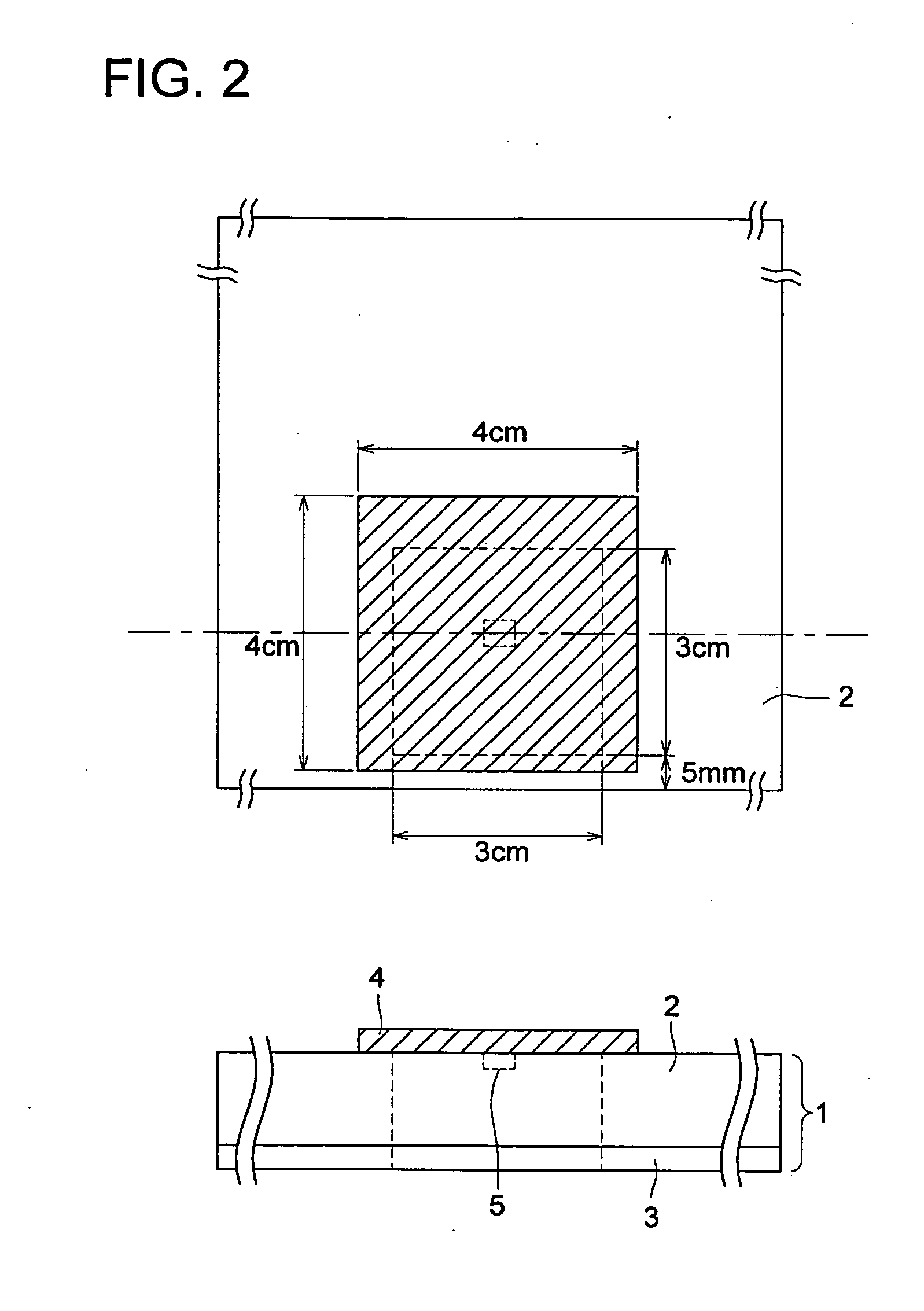
[0338] Next, similar evaluation was performed by changing an adhesion method of an RF-ID on a printing plate into the following 2 types.

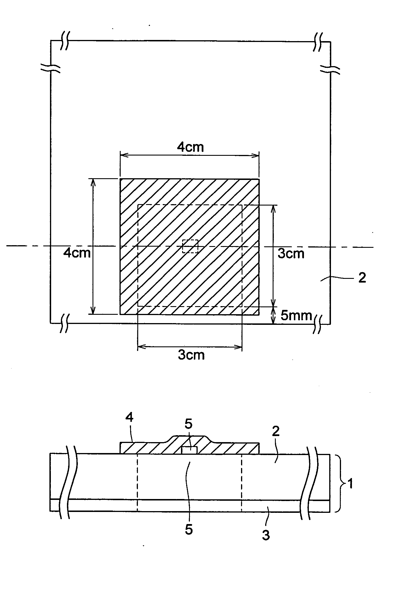
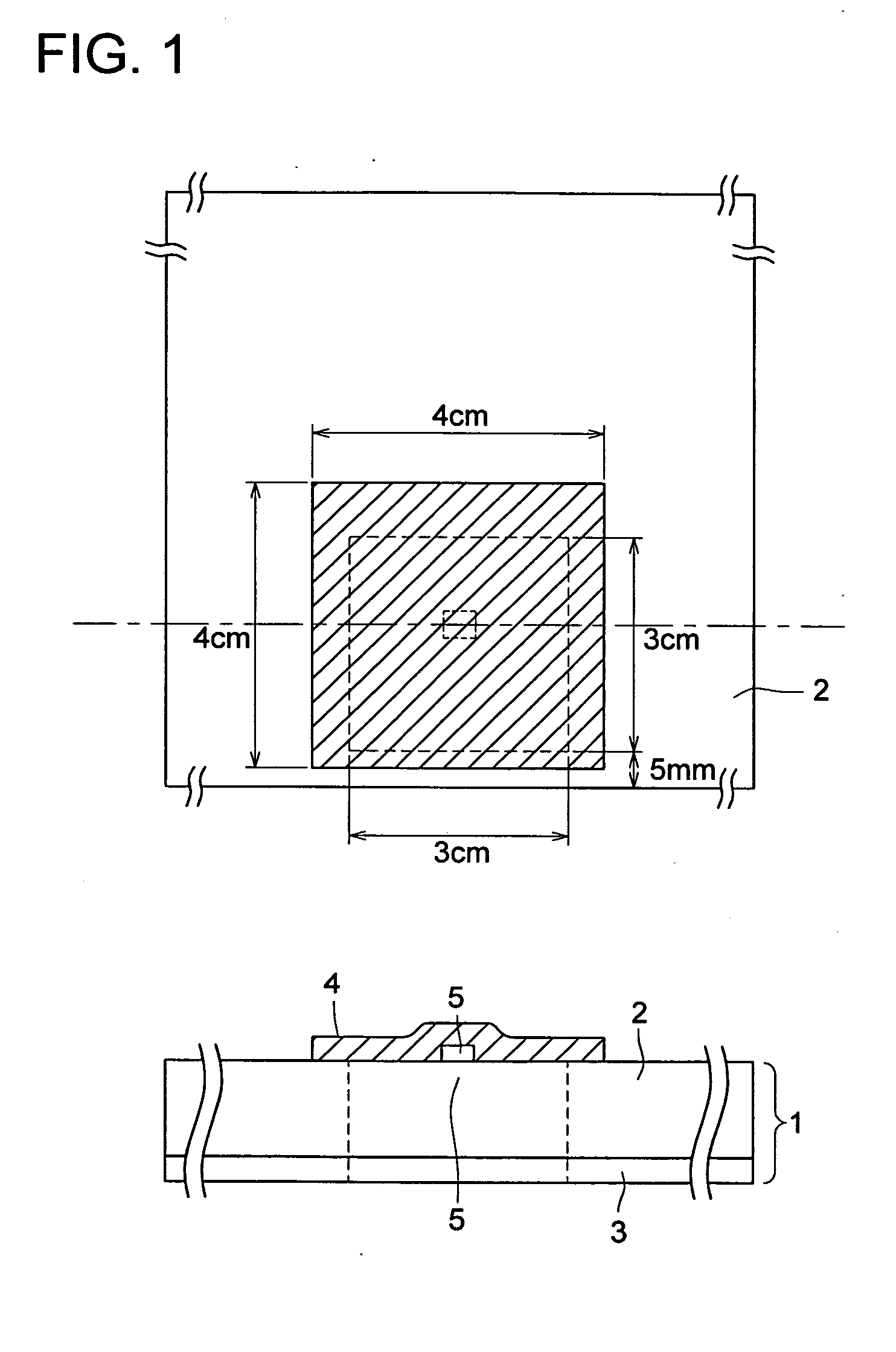
(Adhesion of Wireless Tag (RF-ID) in Protrusion Form)

[0339] A PET film (3 cm×6 cm) having a thickness of 175 μm was pasted on the back surface of a photosensitive planographic printing plate, which had been cut (730 mm wide, 600 mm long) after coating and drying similarly to the above-described manner, at the center portion along the extended longitudinal direction, and an RF-ID similar to one described above was adhered with a double coated tape on the center of a protruded portion (3 cm×3 cm) (mounted in a form shown in FIG. 4).

[0340] Thereafter, by utilizing an RF-ID adhered on the extruded potion as described above, writing / reading was carried out and plate making and printing were performed over half a year.

[0341] The plate making condition was possible to be controlled similarly to the above-described manner, except that time required to ...

example 3

(Feedback to Printing Condition)

[0346] Next, utilizing printing plate material lot 1, plate making was performed in a similar manner to example 1 except the following.

[0347] That is, exposure condition 2 (a mark data in which a rotation number was set slower than an ordinary condition by 20%) was recorded on a wireless tag (an RF-ID) by a writer immediately before laser exposure and exposure was performed under this condition.

[0348] When a mark data was read utilizing a program, which had been set based on printing paper and an exposure condition in advance, by use of an RF-ID reader equipped on a printing machine, a 2-steps feeding paper supply of wood free paper and coated paper was automatically changed into wood free paper to perform printing.

[0349] The printed dot image portion on a printed matter was observed and the result was shown in table 3. As a comparison, the case of an exposure condition being not changed was shown.

[0350] The results are shown in table 3. It is c...


PUM

PropertyMeasurementUnit
thicknessaaaaaaaaaa
thicknessaaaaaaaaaa
lengthaaaaaaaaaa

Abstract

A printing plate material having an aluminum support on which an image forming layer is provided, wherein a wireless IC tag is provided on a part of the printing plate material.

Description

[0001] This application is based on Japanese Patent Application Nos. 2005-010102 filed on Jan. 18, 2005, and 2005-055601 filed on Mar. 1, 2005, in Japanese Patent Office, the entire content of which is hereby incorporated by reference. BACKGROUND OF THE INVENTION [0002] The present invention relates to a printing plate material for a computer-to-plate (hereinafter referred to as CPT) system having an aluminum support, a plate-making method and a printing method. [0003] In recent years, in manufacturing technologies of printing plates for offset printing, there have been developed CPTs for recording digital data of images directly on a photosensitive printing plate with a laser light source, and they have been put to practical use. [0004] In the field of printing where relatively long plate life is required among the aforesaid technologies, there is known a method to use a printing plate material having thereon an aluminum plate representing a support and an image forming layer provi...

Claims


Application Information

Patent Timeline
Patent Type & Authority Applications(United States)
IPC IPC(8): B41N1/00
CPCB41N1/14B41N6/00
Inventor GOTO, KIYOSHI
Owner KONICA MINOLTA MEDICAL & GRAPHICS INC
Why Eureka
Try Eureka