Metal sintered body and production method

a technology production methods, applied in the direction of coatings, etc., can solve the problems of complex component configuration, inability to maintain the reliability of components for a long time, complex logistical administration of components, etc., and achieve the effect of reducing the vacancy ratio, high density and high degree of hardness of metal sintered parts

Inactive Publication Date: 2002-08-06
SEIKO EPSON CORP
View PDF8 Cites 9 Cited by
  • Summary
  • Abstract
  • Description
  • Claims
  • Application Information

AI Technical Summary

Benefits of technology

The sintering procedure under the above-mentioned conditions contributes to the additional reduction of the vacancy ratio; in other words, there is high density & high degree of hardness of the metal sintered part. Simultaneously, it results in rather precise dimensional accuracy, a more efficient sintering effect, and a shorter production time for the sintering process. The sintering operation is also safer. Subsequently, the productivity increases over-all.
The sintering may be conducted in two or more phases. For example, the first sintering process and the second sintering process, which are under different sintering conditions, can be conducted. In this

Problems solved by technology

1) Many components are necessary, so the component logistical administration is complicated.
2) For proper positioning, a concave part and a convex part are needed for the sprocket gear and the ratchet gear, in order to fit or inter-connect with each other, making the component configuration complicated.
3) Because of the low dur

Method used


Image

  • Metal sintered body and production method
  • Metal sintered body and production method

Examples


embodiment 1

Metal powder, which is comprised of the nickel based self-fluxing alloy with an average diameter of 12 .mu.m is prepared. The composition is as follows:

The composition of the binding material is as follows:

The metal power, the binding material and the plasticizer material are combined and mixed with a kneading machine under the 110.degree. C. and 1 hour conditions.

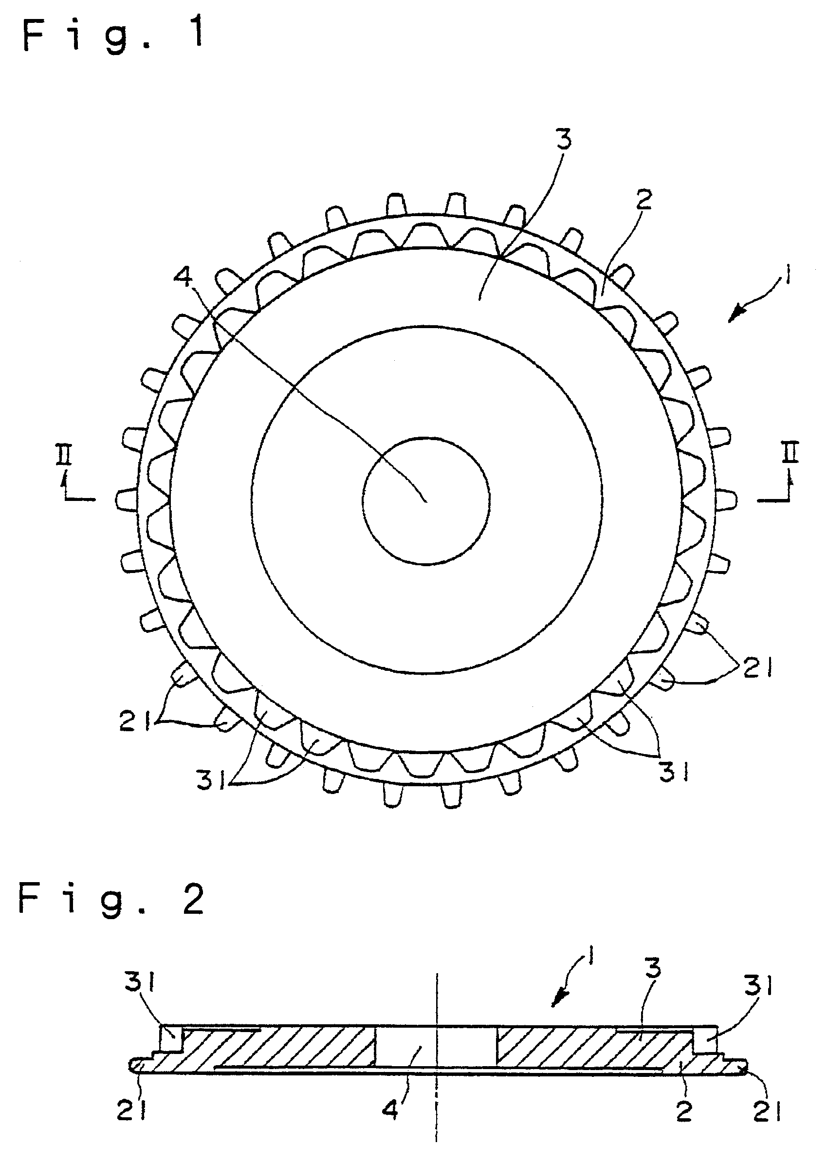
Next, this feed stock is infused by the `metal injection molding (MIM)` method using the injection molding machine. Then, a green body with a shape, which is indicated in FIG. 1 and FIG. 2, is obtained. The molding conditions at the injection molding are (a) mold temperature: 30.degree. C., and (b) injection pressure: 110 kgf / cm.sup.2.

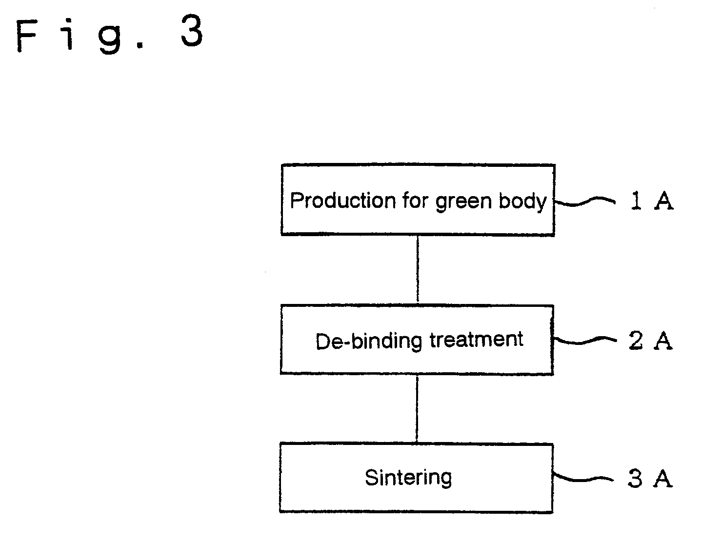
The content amount of the metal powder in the green body is approximately 94.2 wt %. Next, the de-binding process is conducted for the subject green body using the de-binding furnace. The de-binding conditions are (a) under the reduced pressure (1.times.10.sup.-3 Torr), (b) 450.degree. C., an...

embodiment 2

Metal powder, which was comprised of the nickel based self-fluxing alloy with an average diameter of 15 .mu.m is prepared. The metal sintered part is produced with the same procedure as with Embodiment 1, except the metal composition is varied. This composition is as follows:

The characteristics of the produced metal sintered parts (the power transmission component, which are illustrated in FIG. 1 and FIG. 2) for Embodiments 1 and 2 were researched. The results are indicated in the below-mentioned Table 2.

As illustrated in FIG. 2, the metal sintered parts for Embodiments 1 and 2 are confirmed to have the following characteristics: (a) high density (low vacancy rate), (b) high degree of hardness, (c) superior wear resistance, (d) precise dimensional accuracy, (e) no defects, such as crack or deformation. The metal sintered parts were over-all high quality.

As described above, this invention can offer a metal sintered part with a high degree of hardness and a superior wear resistance, a...


PUM

PropertyMeasurementUnit
Linear densityaaaaaaaaaa
Currentaaaaaaaaaa

Abstract

A metal sintered part; the subject of this invention is produced by the following example processes in order to offer the metal sintered part, which has a high degree of hardness and a superior wear resistance, and, in order to offer the uncomplicated production method.Process 1A: To produce a green body, which is manufactured from a metal powder and a binding material, by the metal injection molding (MIM) method.Process 2A: To conduct the de-binding treatment to the green body.Process 3A: To sinter the de-binding body and obtain the metal sintered part.The metal powder for the production is a self-fluxing alloy, such as a nickel based self-fluxing alloy. The surface Vickers hardness Hv of this product is more than value 500.

Description

TECHNOLOGY FIELDThis invention relates to a metal sintered part, which is obtained from sintering metal powder and its production method.PRIOR ART TECHNOLOGYThe following method, referred to as tape automatic bonding (TAB), is utilized in semiconductor mounting technology. (i) Semiconductor chips are fixed on the carrier tape (long length film). They are placed at regular intervals along the edge side of the tape. (ii) The tape is traveled, and these semiconductor chips are conveyed in the manufacturing process. Simultaneously, wire bonding or similar bonding methods are utilized for each semiconductor chip.This carrier tape is given momentum by the following process. (1) The wheel tooth of a sprocket gear engages with an aperture, which is created along the edges of the tape. (2) The turning sprocket gear moves the long length film. This sprocket gear has a ratchet gear, which (a) turns toward one direction, and (b) has multiple ratchet teeth in order to control the spinning amount...

Claims


Application Information

Patent Timeline
IPC IPC(8): B22F3/22C22C1/04B22F3/02B22F1/00B22F5/08
CPCB22F3/22B22F3/225C22C1/0433B22F5/08C22C33/0285B22F3/1021B22F3/10B22F2998/00B22F2998/10B22F3/02
Inventor HAYASHI, JUNICHISAKATA, MASAAKI
Owner SEIKO EPSON CORP
Why Eureka
Try Eureka