Film-coated product cleaning mechanism for optical filter production

A cleaning mechanism and filter technology, which are applied in the directions of cleaning methods, cleaning methods and utensils, chemical instruments and methods using liquids, etc., can solve the overload operation of the working motor, the waste of cleaning liquid spilled, and the secondary pollution of the filter. and other problems to achieve the effect of reducing energy loss, avoiding spillage, and reducing vacancy rate

Pending Publication Date: 2022-01-18
JIANGSU SINA OPTICAL INSTR CO LTD
View PDF10 Cites 2 Cited by
  • Summary
  • Abstract
  • Description
  • Claims
  • Application Information

AI Technical Summary

Problems solved by technology

[0007] (1) By setting the driving motor, the L-shaped transmission rod and the rotating shaft, the driving motor drives the L-shaped transmission rod to rotate, so that the cleaning basket can move up, down, left, and right in conjunction with the rotating shaft, solving the problem of cleaning the optical filter by dragging the water tank in the existing device, Causes the overload operation of the working motor, and also causes the cleaning liquid to spill and cause waste;
[0008] (2) Through the cooperation of the stirring component and the clamping component, the clamping component rotates up and down on the outside of the rotating blade rod, so as to solve the problem that the existing device uses the spiral stirring paddle to stir the cleaning liquid to clean the filter. If there is a cleaning effect, it may also be touched during the stirring process. Encountered the problem of damage to the filter;
[0009] (3) By setting the filter assembly, the filter screen will filter and collect the impurities remaining after cleaning the filter with the cleaning liquid, so that the cleaning liquid is always at a relatively clean level, and solve the problem that the existing device does not filter the cleaning liquid, and there is a problem with the filter The problem of secondary pollution caused by tablets

Method used


Image

  • Film-coated product cleaning mechanism for optical filter production
  • Film-coated product cleaning mechanism for optical filter production
  • Film-coated product cleaning mechanism for optical filter production

Examples


Embodiment 1

[0044] Such as Figure 6-10 As shown, according to the size of the filter, increase or decrease the mounting seat 904 on the outside of the same ring frame 903. The mounting seat 904 slides freely on the outside of the ring frame 903 and is fixed by fastening bolts 907, thereby realizing the control of single cleaning filter. The number of optical sheets, respectively move the first slot 905 and the second slot 906, the first clamping rod 908 and the second clamping rod 909, and move the first clamping rod 908 and the second clamping rod 909 to the same position as the filter The size of the light sheet is roughly consistent with the setting, and then the filter is installed between the first clamping rod 908 and the second clamping rod 909, and the position of the first clamping rod 908 and the second clamping rod 909 is adjusted again, and Fix it by fastening the bolt 907, so that the clamping of the filter by the first clamping rod 908 and the second clamping rod 909 is mor...

Embodiment 2

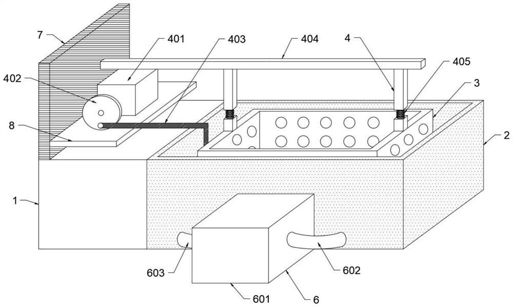
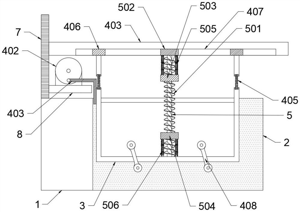
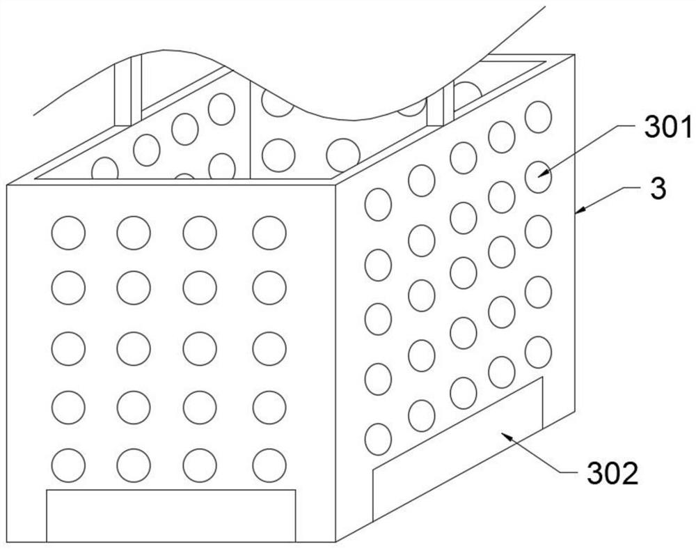
[0047] Such as Figure 1-5 As shown, the stirring assembly 5 includes a rotary blade rod 501, a second slide block 502, a first push block 503, a second push block 504, a second telescopic rod 505 and a third telescopic rod 506, and the quadrilateral rotating cylinder 901 is sleeved on the In the rotary vane rod 501, the top and bottom ends of the quadrilateral rotating cylinder 901 are detachably installed between the first push block 503 and the second push block 504, so that the first push block 503 and the second push block 504 cooperate , driving the quadrilateral rotating cylinder 901 to move up and down while realizing the rotation, increasing the fluidity of the cleaning liquid, so that the cleaning effect of the filter in the cleaning liquid is better. The inside is used to hold the cleaning liquid, which is convenient for cleaning the optical filter. The cleaning tank 2 is equipped with a cleaning basket 3, and the outside of the cleaning basket 3 is uniformly provid...

Embodiment 3

[0050] Such as Figure 1-5 As shown, the water pump 601 continuously filters the cleaning solution through the suction pipe 602 and the outlet pipe 603, the clamping assembly 9 moves up and down in the cleaning basket 3 and rotates, and the cleaned impurities are generated by the rotation of the clamping assembly 9 The vortex flow brings the impurities to the bottom of the washing basket 3, and the impurities are flushed into the filter water tank 604 through the water tank 302 by the water pump 601. The size of the water tank 302 is set to be large, so that the impurities can be washed to the filter water tank 604 in a short time In order to prevent impurities from being brought into the upper layer of the cleaning liquid by the rotation of the clamping assembly 9, the filter will be polluted twice, and the cleaning liquid will be transported to the cleaning tank 2 through the filter screen through the function of the filter water tank 604. 605 filters the impurities of the c...


PUM


Abstract

The invention discloses a film-coated product cleaning mechanism for optical filter production, relates to the technical field of film-coated cleaning of optical filters, and aims to solve the problems that cleaning liquid is scattered and a working motor operates under load when an existing device is used for cleaning the optical filters by moving a water tank, the optical filters are damaged in the stirring process, and the cleaning liquid is not filtered to cause secondary pollution. The mechanism comprises a workbench, a cleaning tank and a cleaning basket. The cleaning tank is fixedly connected to one side of the workbench, the cleaning basket is installed in the cleaning tank, an oscillation assembly is installed above the workbench and acts on the cleaning basket, a stirring assembly is installed in the cleaning basket, a filtering assembly is installed outside the cleaning tank, a vertical plate is fixed to the top of the workbench through spot welding, and a transverse plate is fixedly connected to one side of the vertical plate. Through mutual cooperation of the oscillation assembly, the stirring assembly, the filtering assembly and the clamping assembly, the energy-saving, efficient and cleaner cleaning effect is achieved.

Description

technical field [0001] The invention relates to the technical field of post-coating cleaning of optical filters, in particular to a post-coating product cleaning mechanism used for the production of optical filters. Background technique [0002] A filter is an optical device used to select the required radiation band. A common feature of the filter is that no filter can make the image of the celestial body brighter, because all filters will absorb certain wavelengths. Thus making the object darker. [0003] In the Chinese patent application number 201810926533.0, an energy-saving and high-efficiency communication filter cleaning box is disclosed, including a support column, a base, a cleaning box and a driving wheel. It can fully clean the optical filter in the cleaning box, save a lot of energy, avoid the waste of energy, and also improve the cleaning efficiency, and solve the problem of wasting a lot of water resources due to incomplete cleaning during the cleaning proces...

Claims


Application Information

Patent Timeline
Patent Type & Authority Applications(China)
IPC IPC(8): B08B3/10B08B3/14B08B13/00
CPCB08B3/045B08B3/102B08B3/14B08B13/00
Inventor 张威马帅周常河李长龙刘长宝
Owner JIANGSU SINA OPTICAL INSTR CO LTD
Why Eureka
Try Eureka