Eureka AIR delivers breakthrough ideas for toughest innovation challenges, trusted by R&D personnel around the world.

Circulating system for final assembly vehicle

A technology of circulation system and final assembly, which is applied in the field of circulation system of final assembly, which can solve the problems of high chain cost, easy falling of screws into the chain, elongation, etc.

Pending Publication Date: 2019-11-22
浙江亿睿智能装备有限公司
View PDF0 Cites 1 Cited by
  • Summary
  • Abstract
  • Description
  • Claims
  • Application Information

AI Technical Summary

Problems solved by technology

[0004] However, this method has the following problems. First, because the drive motor of the double-speed chain chain works for a long time, the noise generated is relatively large, and it is not energy-saving; second, because the chain is semi-closed or open, during the assembly process, the screw It is easy to fall into the chain, get stuck in the chain, and damage the equipment. Once the double-speed chain fails, it will easily cause the production line to stop; third, the double-speed chain is a vulnerable part, which is easy to be damaged and stretched, and the cost of replacing the chain is high; Fourth, due to the complex structure of the double-speed chain transmission line, the initial on-site installation time is long and the labor cost is high; fifth, due to the poor transmission stability of the chain transmission, it is not suitable for applications that require long-distance transmission, and the scope of application is narrow; sixth, due to The double-speed chain assembly line runs for a long time during the production process, and the operating part is an open or semi-open structure, which poses certain safety hazards to the workers (such as hair, fingers, and clothing being involved, etc.)
Seventh, individual stations have jacking and rotating requirements, and a jacking and rotating mechanism needs to be installed. The structure of this mechanism is complex and the cost is high
In the case of production changes and process adjustments, the overall layout of the production line needs to be changed, and the change of the line body is time-consuming and laborious

Method used


Image

  • Circulating system for final assembly vehicle
  • Circulating system for final assembly vehicle
  • Circulating system for final assembly vehicle

Examples


Embodiment Construction

[0039] The present disclosure will be further elaborated below in conjunction with the accompanying drawings and specific embodiments. It should be noted here that the descriptions of these embodiments are used to help the understanding of the present disclosure, but are not intended to limit the present disclosure. Specific structural and functional details disclosed herein are for purposes of describing example embodiments of the present disclosure only. This disclosure may, however, be embodied in many alternative forms and should not be construed as limited to the embodiments set forth herein.

[0040] It should be understood that the terms first, second, etc. are only used for distinguishing descriptions, and cannot be interpreted as indicating or implying relative importance. Although the terms first, second, etc. may be used herein to describe various elements, these elements should not be limited by these terms. These terms are only used to distinguish one unit from ...


PUM


Abstract

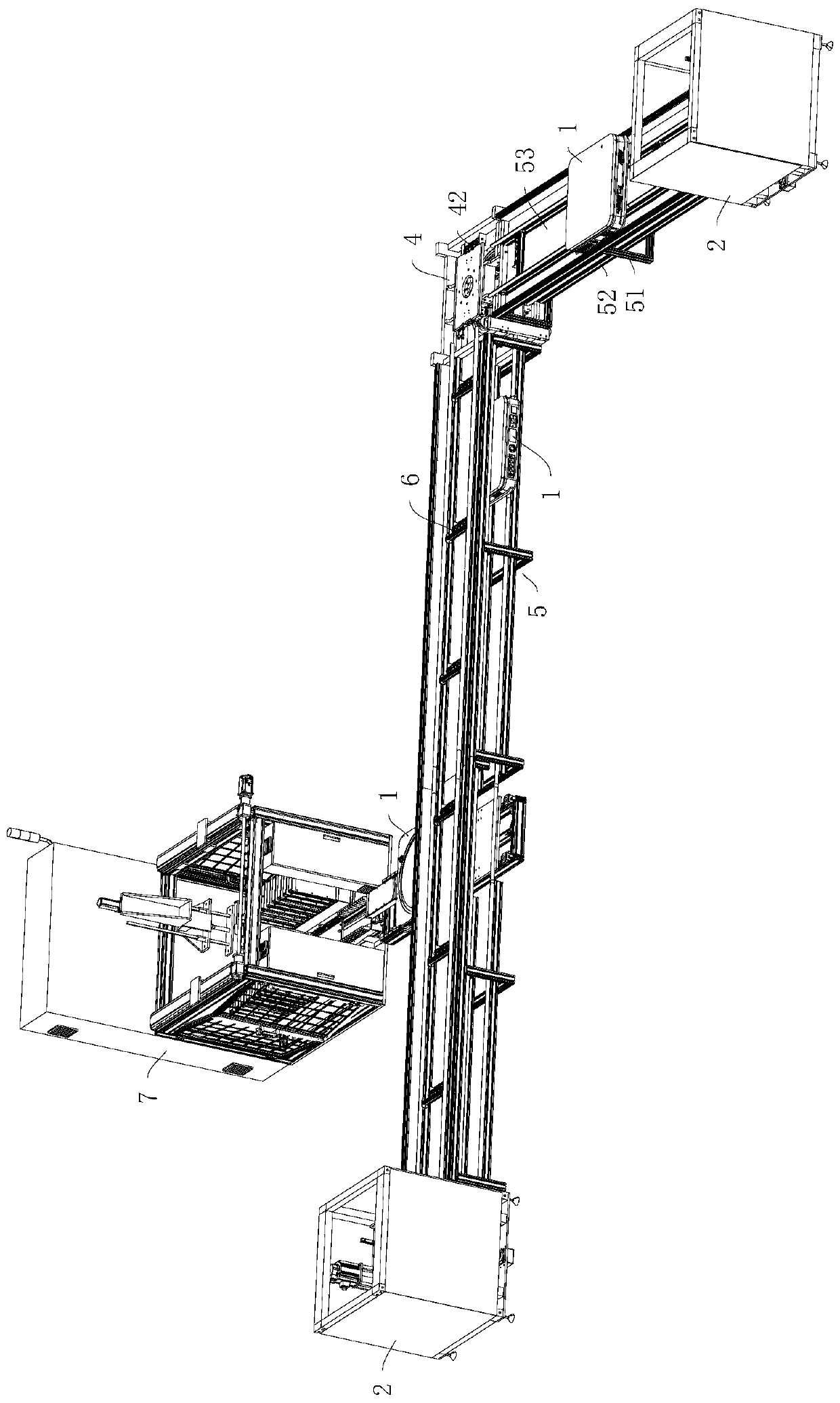
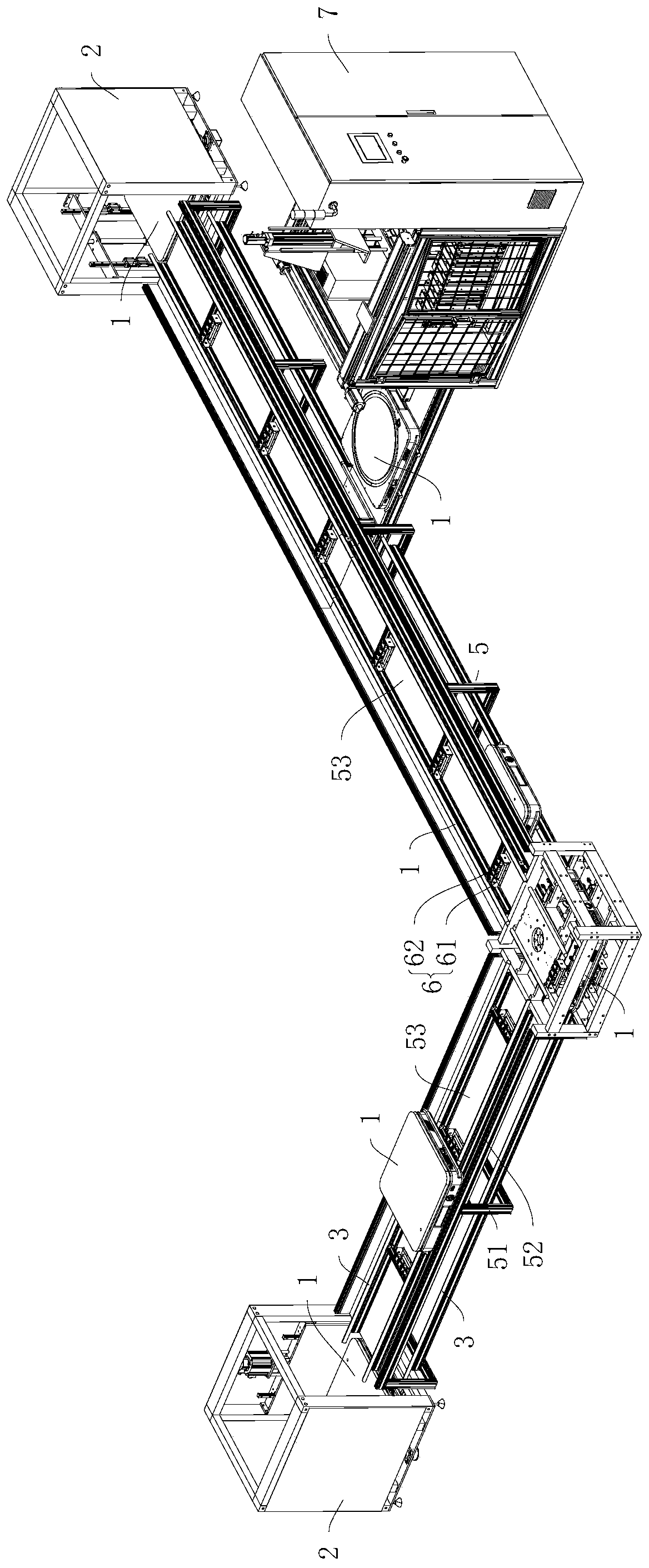
The invention relates to a circulating system for a final assembly vehicle. The circulating system comprises two lifting devices for lifting or landing the final assembly vehicle, multilayered tracksfor guiding the final assembly vehicle to move and a rotating device for adjusting orientation of the final assembly vehicle. The vertical separation distance between adjacent two tracks is greater than the height of the final assembly vehicle. The rotating device comprises multiple rotating mechanisms corresponding to the tracks one by one and the rotating mechanisms are used for bearing the final assembly vehicle and driving the final assembly vehicle to rotate, and connecting tracks of the rotating mechanisms can be aligned to the end parts of the tracks, so that the final assembly vehiclecan travel to the tracks from the connecting tracks or travel to the connecting tracks from the tracks. Joining tracks of the two lifting devices can be aligned with the end parts of the tracks, separately, so that the final assembly vehicle can travel from the joining tracks to the tracks or travel from the tracks to the joining tracks. The joining tracks, the connecting tracks and the tracks jointly form a circular traveling circuit of the final assembly vehicle. Therefore, the final assembly vehicle is circularly used, and the stability of the final assembly vehicle in the travelling process is improved.

Description

technical field [0001] The present disclosure relates to the technical field of product conveying equipment, in particular, to a circulation system for final assembly vehicles. Background technique [0002] The assembly line refers to the production line in which the workpiece passes through a series of assembly workstations continuously and evenly at a certain rate, and completes the corresponding assembly work at each assembly workstation according to certain requirements. [0003] At present, the assembly line in the industry mainly adopts the method of double speed chain. A typical double-speed chain assembly line is mainly composed of a tooling plate, a stop mechanism, a double-speed chain, a drive motor, and a chain tension adjustment mechanism. Specifically, the tooling board is arranged on the double-speed chain, so that it can move on the assembly line driven by the driving motor. [0004] However, this method has the following problems. First, because the drive m...

Claims


Application Information

Patent Timeline
IPC IPC(8): B23P21/00
CPCB23P21/004B23P19/008
Inventor 俞崇喜
Owner 浙江亿睿智能装备有限公司
Why Eureka
Eureka Blog
Learn More