
Perpendicular magnetic recording head and perpendicular magnetic recording and reproducing system

a perpendicular magnetic and recording head technology, applied in the field of magnetic recording head for perpendicular recording and to perpendicular magnetic recording and reproducing system, can solve the problems of disadvantageous thermal demagnetization, erasing recorded data, and small residual component of old data remaining after erasing, and achieve excellent overwrite property. excellent

Inactive Publication Date: 2006-12-05
HITACHI GLOBAL STORAGE TECH JAPAN LTD +1
View PDF11 Cites 7 Cited by
  • Summary
  • Abstract
  • Description
  • Claims
  • Application Information

AI Technical Summary

Benefits of technology

The present invention provides a perpendicular magnetic head with a novel structure that reduces magnetic interference and prevents deterioration of the overwrite property during high-density recording. This improves the write erase ratio of the perpendicular magnetic head and prevents the deterioration of the overwrite property in a perpendicular magnetic recording and reproducing system. The technical effects of the invention include a reduction in magnetic interference and improved write erase ratio, which prevent deterioration of the overwrite property during high-density recording.

Problems solved by technology

This causes the problem that the resulting thermal disorder erases recorded data.
An important issue in adopting the direct overwrite method is that a residual component of old data remaining after erasing is sufficiently small when new data is written directly over the old data.
If the occurrence of the situation is frequent, thermal demagnetization is accelerated disadvantageously in the recording magnetization of the adjacent track.
As a result, interference from the previous history magnetization with a recording point shifts the magnetic transition point (transition point shift), which degrades the overwrite erase ratio.
As shown in the report, in a perpendicular magnetic head and a perpendicular magnetic recording and reproducing system using the same, the prevention of the degraded overwrite property caused by a reduction in the film thickness of the first magnetic pole or recording magnetic pole of the magnetic head is an important issue.

Method used


Image

  • Perpendicular magnetic recording head and perpendicular magnetic recording and reproducing system
  • Perpendicular magnetic recording head and perpendicular magnetic recording and reproducing system
  • Perpendicular magnetic recording head and perpendicular magnetic recording and reproducing system

Examples


embodiment 1

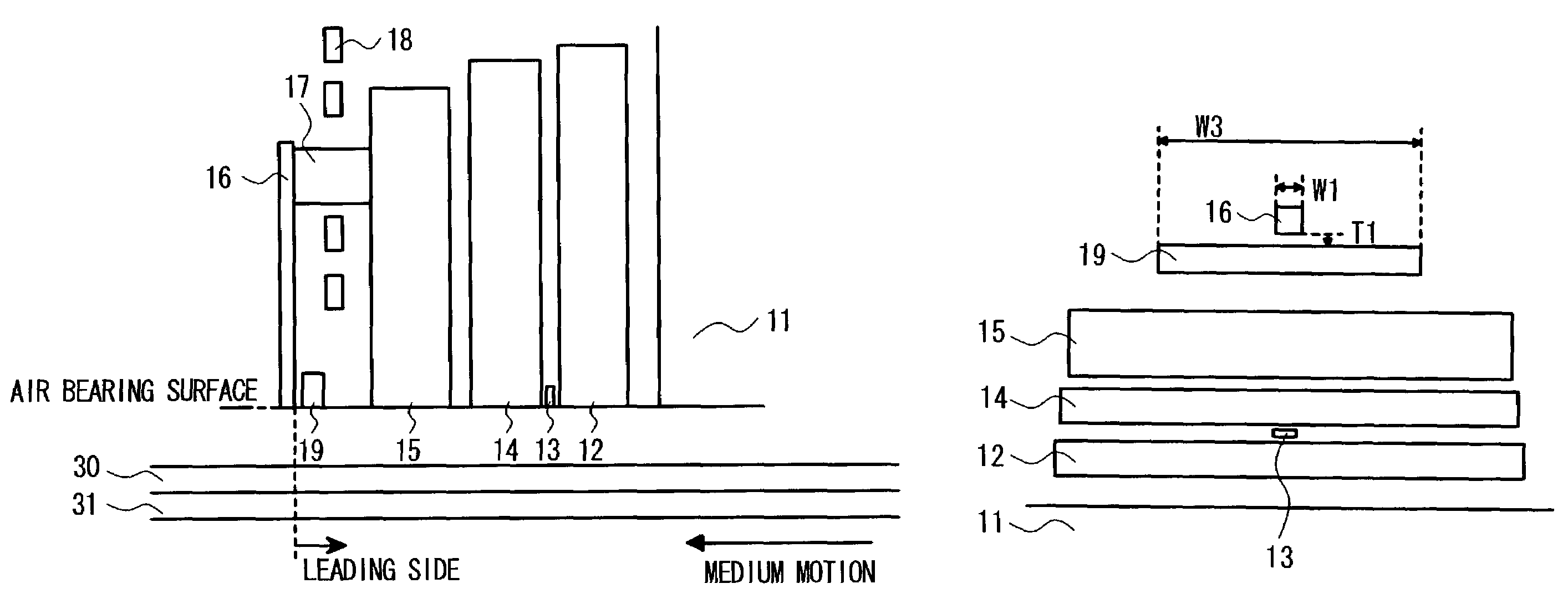
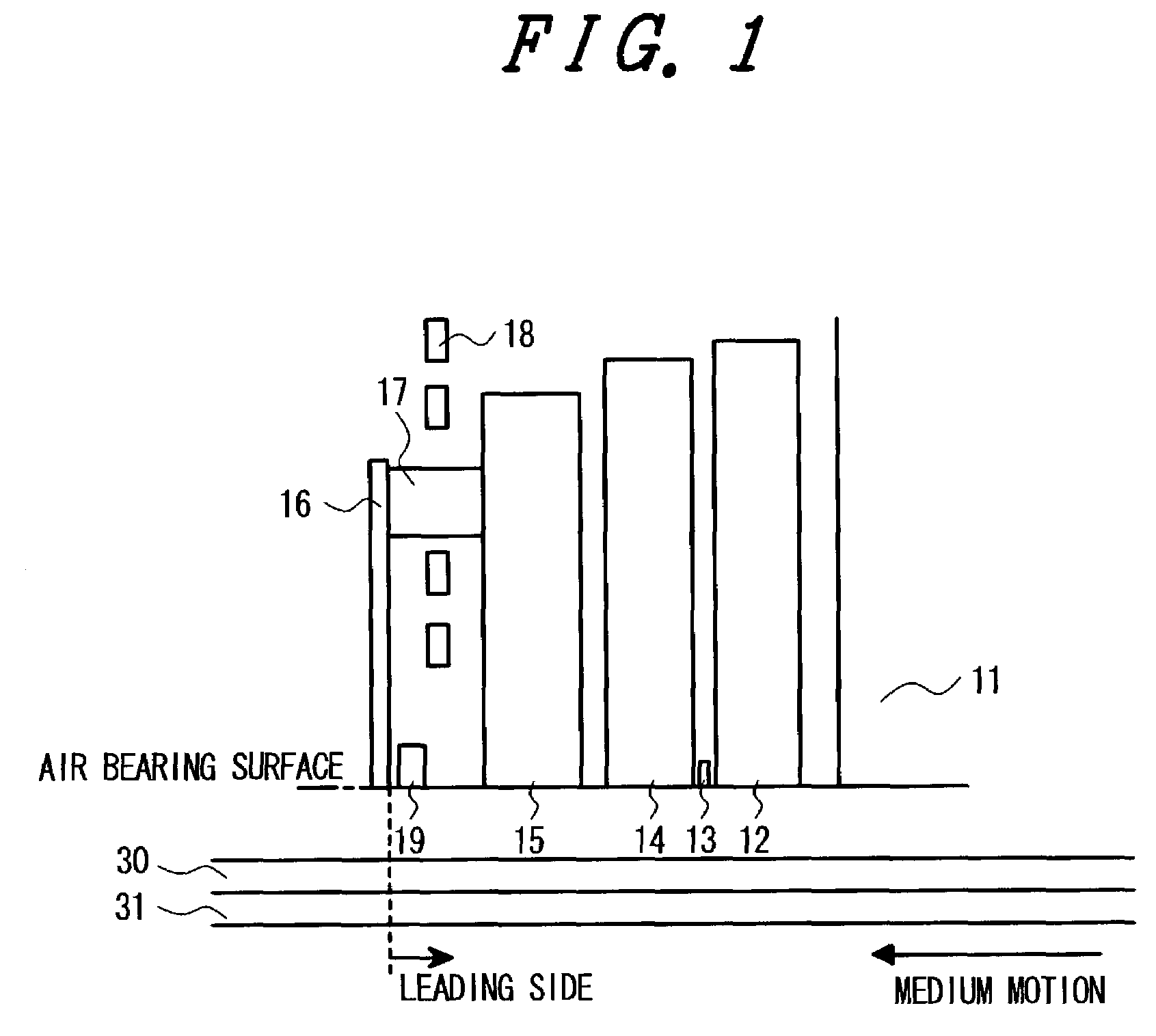
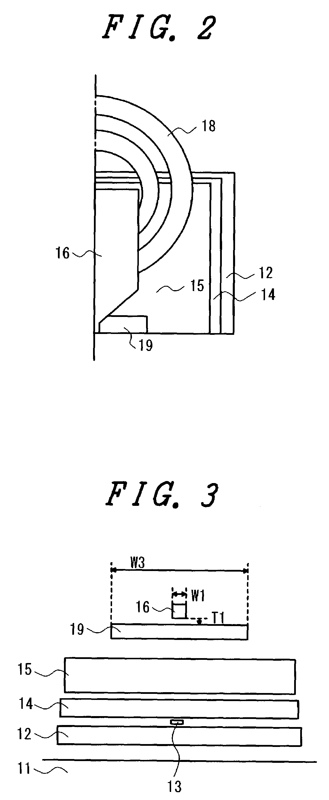
[0037]FIGS. 1 to 3 show the structure of a magnetic head for perpendicular recording (hereinafter referred to as the perpendicular magnetic head) according to a first embodiment of the present invention, of which FIG. 1 is a cross-sectional view of the magnetic head showing a surface perpendicular to each of an air bearing surface and a substrate surface, FIG. 2 is a plan view of the magnetic head showing the right-hand half of the surface perpendicular to each of the air bearing surface and the substrate surface, and FIG. 3 shows the air bearing surface of the magnetic head. In the drawings, 11 denotes a substrate, 12 denotes a lower shield, 13 denotes a magneto-resistive effect film, 14 denotes an upper shield, 15 denotes a second magnetic pole or auxiliary magnetic pole, 16 denotes a first magnetic pole or recording magnetic pole, 17 denotes a back yoke portion, 18 denotes a coil, 19 denotes a third magnetic pole 19 provided on the leading edge side, i.e., leading side in the dir...

embodiment 2

[0044]FIGS. 4 and 5 show the structure of a magnetic head according to a second embodiment of the present invention, of which FIG. 4 is a cross-sectional view thereof and FIG. 5 shows the air bearing surface thereof. For the magneto-resistive effect film 13 of the reproducing portion of the magnetic head according to the second embodiment, a TMR (tunnel magneto-resistive effect) film or a GMR (giant magneto-resistive effect) film is used. A pair of electrodes connected electrically to read a signal from the magneto-resistive effect film are connected to the upper and lower sides of the magneto-resistive effect film 13 in the direction of the film thickness thereof. A magnetic domain control layer is also connected to the magneto-resistive effect film, though it is not depicted. After such a reproducing portion is fabricated, a recording portion is fabricated by forming a first magnetic pole or recording magnetic pole 16 composed of a soft magnetic layer, an auxiliary magnetic pole o...

embodiment 3

[0046]FIG. 10 shows the air bearing surface of a perpendicular magnetic head according to a third embodiment of the present invention. Although the cross-sectional and plan views of the third embodiment are the same as those of the first embodiment, the air bearing surface of the third embodiment is different from that of the first embodiment. As shown in FIG. 10, the flat portion of the magnetic film forming the third magnetic pole closer to the first magnetic pole has a width equal to that of the first magnetic pole and the film thickness of the third magnetic pole are gradually reduced with distance from the first magnetic pole. Even the third magnetic pole having such a configuration achieves effects equal to those achieved by the third magnetic pole according to the first embodiment. In this case, the third magnetic pole can be formed extremely easily and conveniently by performing overmilling in forming the first magnetic pole 16 by ion milling.


PUM

PropertyMeasurementUnit
distanceaaaaaaaaaa
distanceaaaaaaaaaa
distanceaaaaaaaaaa

Abstract

There is provided a perpendicular magnetic recording and reproducing system in which the overwrite erase ratio of a perpendicular magnetic head has been improved to prevent the deterioration of an overwrite property. In the perpendicular magnetic head, a third magnetic pole composed of a soft magnetic layer is formed on the leading side of a recording magnetic pole via a non-magnetic layer, thereby reducing magnetic interference from magnetization on a medium with the recording magnetic pole and preventing the deterioration of the overwrite property.

Description

BACKGROUND OF THE INVENTION[0001]1. Field of the Invention[0002]The present invention relates to a magnetic head for perpendicular recording and to a perpendicular magnetic recording and reproducing system.[0003]2. Description of Related Art[0004]In recent years, a hard disk drive which is a magnetic recording and reproducing system used as an external recording device for an information processor, such as a computer, has been required continuously to be increased in capacity and reduced in size. To meet the requirements, improvements have been made primarily in the recording density of the hard disk drive. If the density is increased by using a conventional longitudinal recording method, however, it is necessary to reduce the thickness of a recording layer since a demagnetizing field becomes maximum on the magnetic transition zone of a recording medium upon recording magnetization. This causes the problem that the resulting thermal disorder erases recorded data. By contrast, a perp...

Claims


Application Information

Patent Timeline
Patent Type & Authority Patents(United States)
IPC IPC(8): G11B5/127G11B5/00G11B5/09G11B5/187G11B5/31G11B5/39
CPCG11B5/09G11B5/1278G11B5/187G11B5/313G11B5/3967G11B2005/0029
Inventor KIMURA, HISASHINAKAMOTO, KAZUHIROKAWATO, YOSHIAKIYOSHIDA, NOBUO
Owner HITACHI GLOBAL STORAGE TECH JAPAN LTD
Learn More